Hmm It is very odd symptoms indeed, as you’d ordinarily see the first nintendo logo (boot CPU afaik) long before the secondary CPU rail comes up (around the same time as the second logo) - ordinarily in this scenario with the black screen and no boot logos stock - you’d expect the secondary CPU rail to be low and for something else to be halting boot (given no logos, something very early on in the boot process) - As you say fuses would have been a possiblity if booting stock standard (but secondary CPU rail would still be low afaik) and Hekate bypassis this when “booting stock/cfw” - so can rule that out. The GPU reg comes up pretty much in tandem with the secondary CPU rail ordinarily (pretty much the same time the second switch logo would display)
Sorry I haven’t used Hekate in ages so don’t recall if it’s on the page in the image you postedor elsewhere. but I’m pretty sure on one of the pages it does ID the CPU and GPU regs (at least if I’m remembering right) if it’s not Identifying them then that might be pointing to the problem.
What is the behaviour currently, is the output high the moment your prompt the console to boot or is there a few seconds delay until the output comes on?
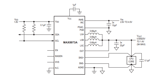
Yes in hekate’s battery page it shows ‘CPU/GPU PMIC’ as max77621 v18
The amp draw goes to 0.08 (with nothing connected other than nand) maybe half a second or so after the console is prompted to boot, definitely not instant, seems to be about the same time a working switch goes from 0.0a to 0.08a, of course the working board I tested (with nothing connected other than nand) goes from 0.0a to 0.08a then back to 0.0a
Perhaps it is a bad connection under the soc, there is a few traces that link the soc to both regulators, maybe the cpu reg just isn’t being told to enable which halts the boot
I see, then this reinforces them likely being fine then.
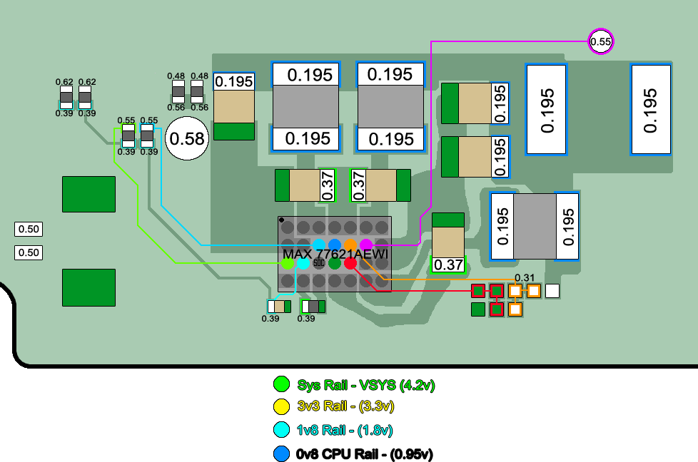
Sorry, I should clarify. I mean the voltage at the (secondary) CPU reg output inductor, the one below the SoC. Ordinarily the voltage woud be low until the boot CPU has done it’s thing and the hand off begins then this secondary CPU rail comes up (anywhere from 0.8 to 1.4V) a few secs later (this would be around the same time as the second Switch logo shows up on a working switch) - If the output is high directly following prompt then it might indicate issues SoC side.for example.
Sorry I’m not really familiar with using the Switch adapter at the higher voltage when testing current status (I’m guessing that’s what your using right?) as I typically use a 5V USB and the behaviour is quite a bit different.
Maybe, but given the output voltage is high on this rail it’d be more likely the otherway round, potentially told to enable to soon or stuck on.
I meant to say maybe the gpu reg isn’t being told to enable which halts the boot, my bad
I will try to see how fast the voltage comes up on the cpu regulator if i can figure out a good way to hold the probes and prompt it to boot
Also yes I use the official 15v nintendo charger when checking the amp draw using my uni-t am meter
So I soldered some wire to keep it connected to my multimeter to watch the voltage on the cpu regulator, it starts about 1 second after I connect the usb.
It doesn’t immediately jump to 0.95v but it also doesn’t take more than 2 seconds so hard to say since I don’t have a working switch board to check it against anymore
Also when you say the voltage should be low until the boot cpu is done, how low? I see either 0.0v or 0.95v once it enables
I haven’t got a switch to hand but looking at a few vids and it looks like anywhere from 3 to 5 seconds for that second logo to show up which is about when I’d expect this secondary CPU rail to come up. So provided I’m correct and this rail is coming up too soon then that may be your issue - but, afair the outputs on this IC are enabled serially over I2C and not via some GPIO / dedicated enable line - - maybe there is a joint issue from the SoC or a failure to communicate between the two and maybe this is this Max IC’s default behaviour in this situation to simply throw it’s hands in the air and default to enabling the output .(though I could be wrong) - If I remember right there is a couple of resistors very close by pulling a few lines up to 1V8PDR, you never know, you might get lucky and find these resistors have bad encaps or something when measuring directly on the traces otherwise it will likely be the other lines directly off to the SoC. - It might be worth checking the USB current behaviour with a 5V supply just to see if anything differs.
I know @SheriffBuck is a lot more well versed on the I2C protocol than I am and has done some work in this area, maybe he can let you know. The part that’s got me is Hekate seems to be having no issues communicating with them (assuming it’s truly talking to both)
I’ve been making an image of the various readings similar to calvins using this board and been over the board many times and every resistor has checked out and appears to be fine so sadly I won’t be getting that lucky
The 1v8 that goes to the cpu reg can be checked on the cap just below it and it has the expected 1.8v when I check
So I’m starting to consider an soc reball, I’ve reballed one switch soc so far and was successful with it, though I don’t have the stencil and will do it by hand again
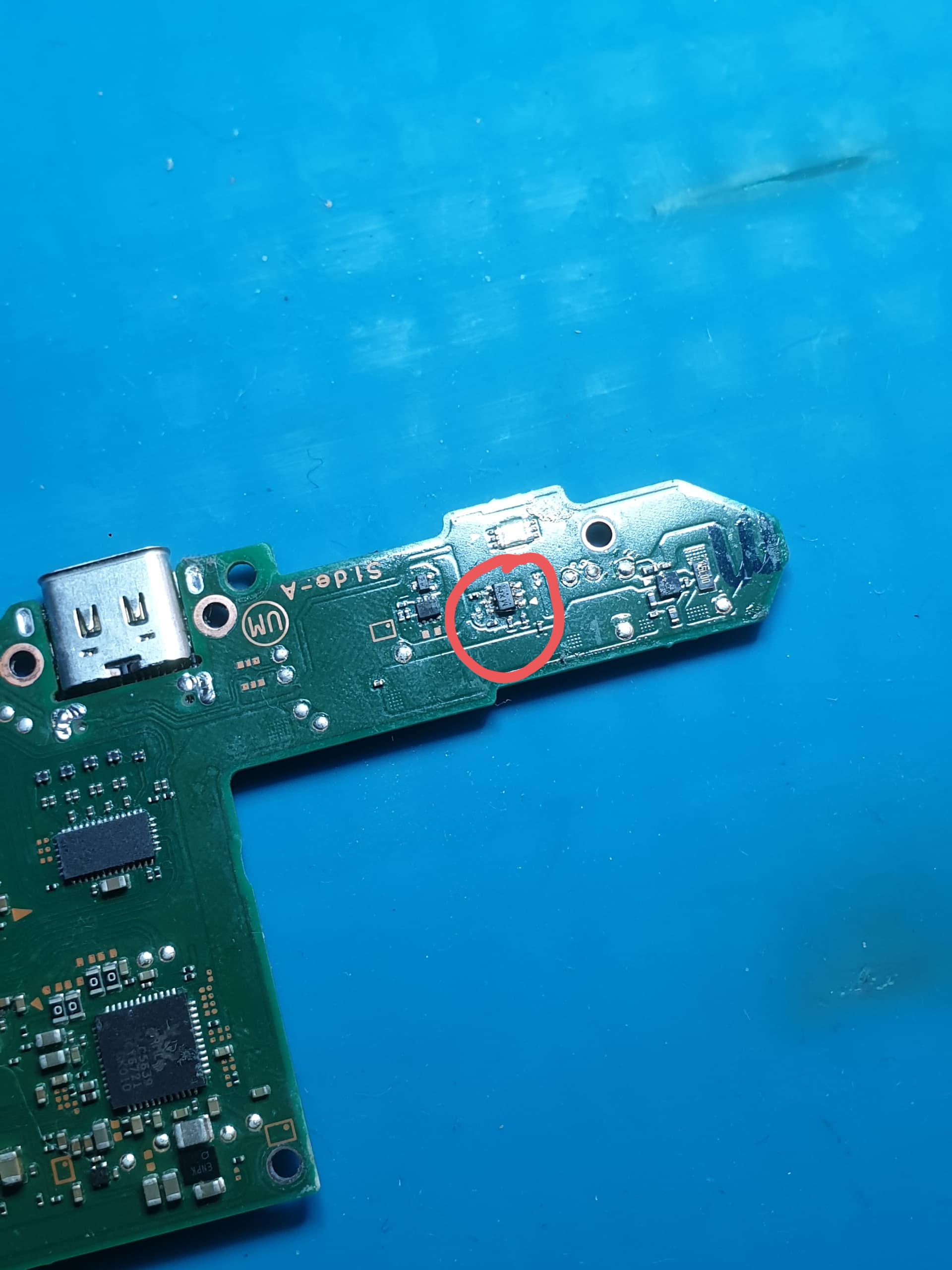
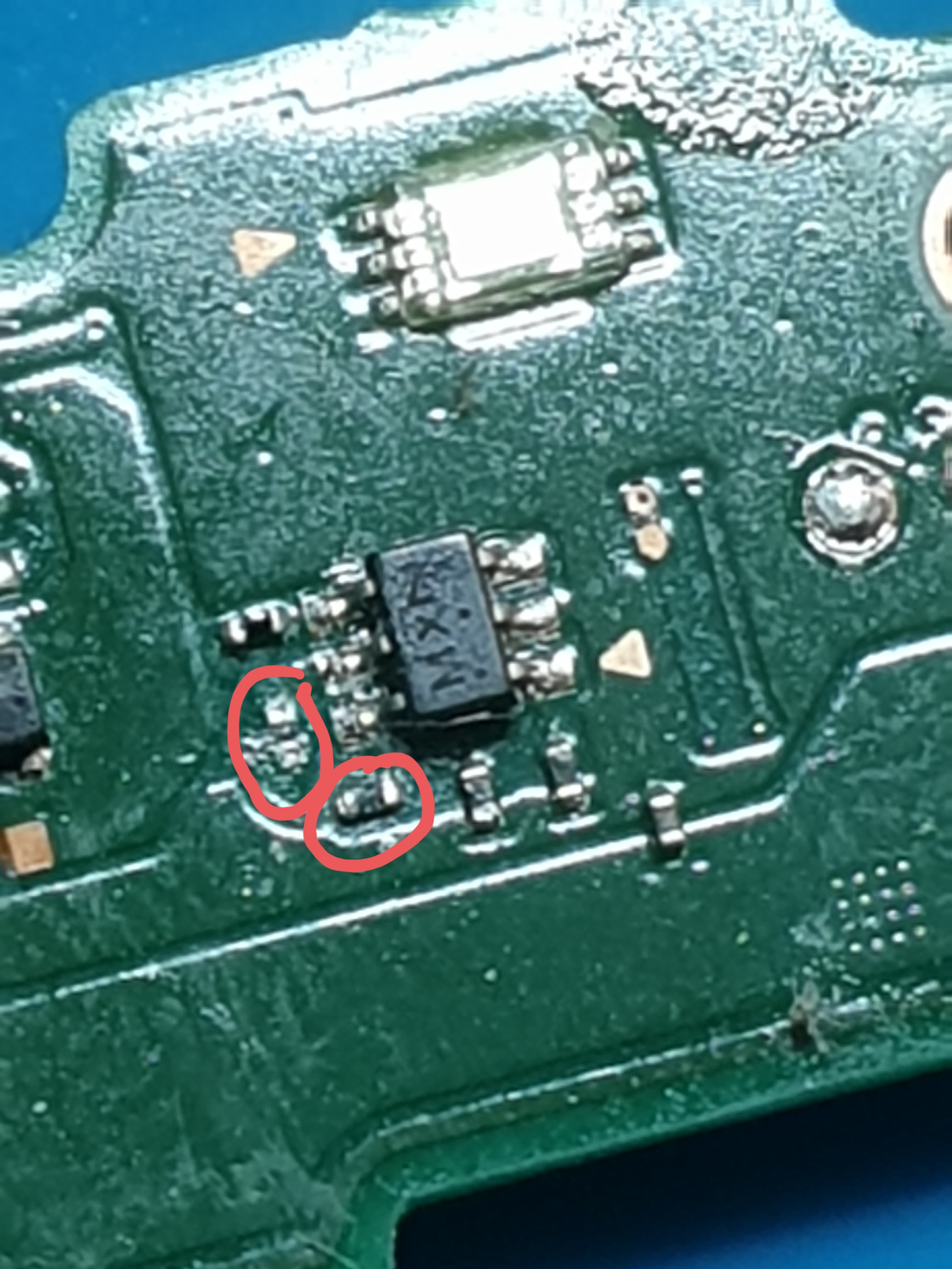
Hi I have a nintendo switch that came for usb c replacement and the repair went well and i tried to turn it on but the switch screen was black with backlight on after sometimes of charge the display worked and after sometimes it went back black again with backlight on, since then i tried to reset and still the same , so i took apart the switch for visual inspection i found a resistor missing and another resister looks like broken maybe it could have happened while repair, but i do not know the values of those resistors if someone could help me would greatly appreciated, i have added some mage of those resistors location below
You may well know I’m not too fond of taking measurments in this way - atleast outside of a quick and dirty check as, as you probably already know, in certain instances (and most likely this instance) when you’ve got high ohm resistors acting as pullups (and other instances too), the resistor/s endcaps could be bad (separated fron the carbon) and you can measure a “good” diode mode reading either end - in this case it would be whatever diode reading the CPU reg I/O gives independently and on the otherside whatever 1V8PDR would ordinarily give - which doesn’t really tell you much of anything if the resistor ordinarily has a negligible affect on the overall circuit (diode mode) and the resitor could still be bad… I’m very sure that you’ve already checked these resistors properly anyway but just thought I’d mention this for anyone else
seems a little low to me - Can you provide me some photos front and back of the board and then some of closups at the usual locations such as BQ, M92, Battery connector, all areas which we covered above. Sometimes a fresh pair of eyes can catch something.
Try not to be fooled by these situations, this rail could be coming by way [of some other via/layer] which this cap resides on (which I’m pretty sure it is) , just because your measuring the rails voltage there doesn’t tell you if the resistor is open.
I don’t envy you there but would advise against this - Switch SoC is very intolerant to heat. I imagine when your doing this by hand your doing it in segments? Given that you’ve put it through another rework cycle pulling the IC, your then doing it all over again while manually placing the balls multiple times and then yet again at the end when placing the IC on the board. If the SoC is still alive by the end I wouldn’t not fancy it’s long term survival I’d just pick up a proper 90x90 stencil, think they’re like 10 quid last I checked
CPU buck as you say comes on almost instantly after the system powers up.
GPU buck IIRC doesn’t normally fire up until after the Switch logo and Horizon GUI properly launches
I have a payload that’s not been properly finished that’s based on Hekate. You can turn on and off the bucks and test a few other things. Might be useful for debug purposes.
Both bucks have feedback loops which lift power off another TEGRA SOC pin and feeds it back to the MAX. I’d expect to see no more than 0v8 on both bucks. Anything higher suggests the feedback loop may have failed and the circuit is open loop.
I’d avoid reflowing SOC or refitting RAM at this point. Probably a few more diagnostic stages beforehand. The more you rework things, the more variables and failure modes you can create which will compound identifying the original core fault.
I’d suggest sniffing I2C Port 0 and Port 4 to check for valid traffic and negotiations. It’s also useful to watch data access on the EMMC on D0 as that can give you a sense of just how far things are getting on the boot process. I can help identify the locations, but there are two pull-up resistors near the MAX7621 and some convenient pads near the M92 that you can use to get to both serial busses. You can familiarise yourself with my other recent postings around a similar issue with an OLED.
Do you have a logic analyser handy? (They are two a penny on ebay if you want a cheap and cheerful copy that will do the job)
I must be remembering wrong, I thought it was pretty well synced up time wise in the time it takes high current charge to initilise / second logo at approx 2 to 5 secs.
Ah fair enough, how was your time on that out of curiosity
I wouldn’t use paste on a chip of this size, bit of a nightmare tbh as it’s near impossible keeping the stencil flat and the balls all even - then when it all goes wrong you have to wick and start the process all over putting the SoC through yet more stress. I’d use jig and preformed balls in conjunction with the stencil (assuming you’ve got the right one) - not saying it’s impossible with paste, just a bit of a pita, requires a lot of practice and is not very repeatable (especially as the paste gets old)
Logic analyser is best as you can actually decode the messages on the bus and determine if anything is silent despite repeated requests etc. You can pick up one for $20-$25 and is an essential weapon IMHO.
I’ll try and tidy up the code so it’s in a releasable state. Drop me an PM and I can probably get you a prerelease payload to test with.
Make sure the SNS+ and SNS- are actually getting a signal - these close the loop for the MAX to control output current/voltage. I had one Switch where the unit wouldn’t boot because these lines had failed. You can jumper the output direclty onto them if needed.
Then I will need to shop some more, I bought the one designed for paste with square holes no rush since I hope a reball won’t be required for this.
Also I should say when I test resistors, I test in resistance mode on both ends of the resistor then reverse probes and test again, in circuit naturally, I rather not pull each and every tiny resistor