I’ll check that on the next working switch I come across, though timing it would be really hard
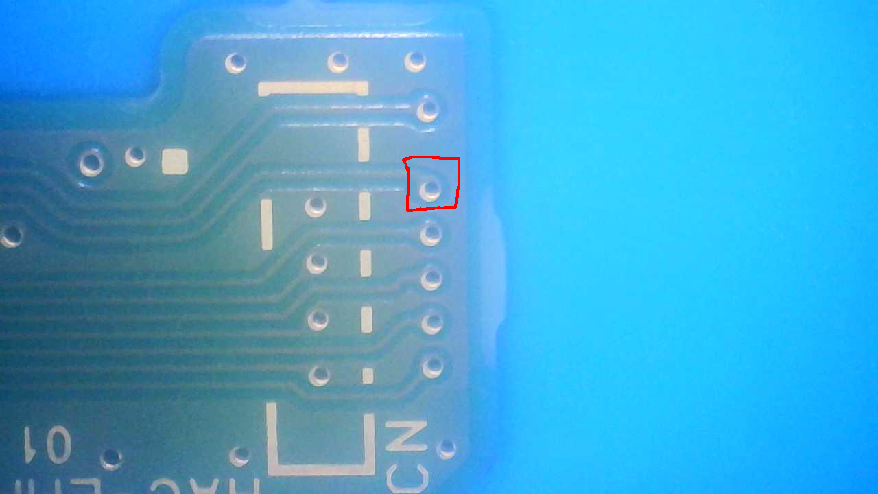
I don’t suppose you know if there should be voltage on the outlined nand via when the board is powered on?
The nand is the only other component that followed the SoC to the new board, so I stuck the original nand on to test and that via has 0.90v on it, while with the matching nand there is no voltage.
I made sure both boards were in rcm mode before checking the voltage
Excuse the blurry microscope image, my microscope is crapping out on me it seems
Doesn’t have to be super precise. My memory is the time it took for this rail to come up correlated pretty well for the time it took high current charge to initiate. So plug in the USB, 0.4A (approx), drop to zero, high current, when high current is initiated CPU buck output should come up in around this time - so just probe [secondary] CPU output up until that point. Though like I say I may well be remembering this all wrong… maybe I’m confusing it for the GPU buck or something or maybe things have changed in an update.
according to my info that is the EMMC CLK line - I don’t recall if if this is active prior to prompt (i don’t imagine it is) but given your symptoms it’s not that surprising it’s not showing you anything in this case.
My understanding of the EMMC protocol is limited and what little I do know was from well over a year ago but afair the SoC would have to trigger something on the CMD line to initiate the EMMC, CLK would initiate somewhere before or around this time, it woud then start in single bit mode (exclusively using DAT0) - So I suppose if the suspect bad EMMC is haywire then perhaps clock is stuck high… can you check if it’s a valid clock signal using your LA? perhaps it’s just stuck as a logic high and nothings happening?
Though as I say, take all I say with a pinch of salt, I really need to brush up on this
Which LA have you got? Most I’ve seen just give the I/O numbers or “CH#” (channels) with the only I/O you should be concerned with getting a corralated connection being the labeled ground. So for example you should be able to hook up channel 5 of the LA to CLK or channel 8 of the LA to DAT0 etc in other words order doesn’t matter so long as you know where they are going (and you should be able to name these channels in software for easier ID)
A cheapo one, has CH1 through CH8, CLK and CND, no label specifying ground, however the image from the amazon listing for this LA has CND as GND in the label image, so I can assume CND is GND
I see then use I’d any of the “CH#” to connect up to the lines of the EMMC - ignore the CLK input on the LA for now (perhaps it’s the internal clk signal, or maybe it can deal with faster frequencies on this I/O ) either way you should be able to monitor all the signals of the EMMC on the “CH#” marked I/O on the LA (including EMMC CLK) - Yeah I imagine it’s a misprint and CND is GND you’ll want to make sure that you’ve got the GND of your LA hooked up to the boards ground.
I imagine this will be using Sigrok or some modified version of it so you can name all your channels in the software to reflect the EMMC I/O
Though what I’d say - as you have one EMMC which is bad (right?) and another which is suspected good I don’t know how much this will tell your in all honesty and it could be that the SoC is working enough to start issuing read commands of the eMMC but not much more beyond that… hard to say either way I suppose this is good practice for you later on down the line
Yeah this is more to learn how to use the LA, considering that the only original components is the nand and soc on the transplant board and I’ve dumped the nand in the past, I am sure it is the soc and is not fixable.
I’ll play around with the LA and see what I can figure out, then eventually get a fully working switch to check the differences
Interesting story, I am facing the exact same situation. After a water damage undergone by the MAX77621 IC, I reflowed it, and I could then inject hekate payload and load it. Whatever the FW I only have blackscreen. Must I infer this is a SoC issue? What would you suggest first to confirm 100% this is it?