Hi guys!
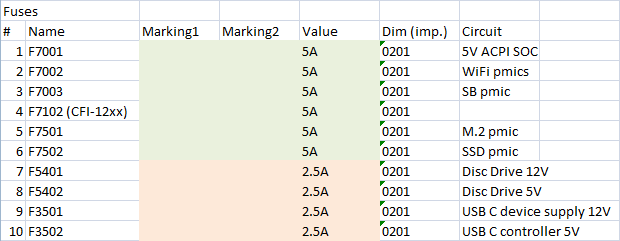
I have a blown 7002 fuse in a EDM-040 board. I have another 041 board that I borrowed from a friend and this fuse looks slightly “different” than the one in the 040 board by color and maybe by symbol, I’ll elaborate, the 040 has like a darker tone color tan the 041, and sincerely I can’t see if this is a minus symbol or nothing on it, could anyone please check it out and tell me which fuse do I need? See image down below
ht tps:/ /ibb. co/ 0RCy492T
ht tps:/ /ibb. co/ hR2P9hcz
Also, I have a diode with no reading in one side where is supposed to be a reading, this diode is closer to the HDMI encoder IC. See image down below
ht tps:/ /ibb. co/ nvrgRXB
Now the story behind all this trouble. This unit 040 came with a beep on beep off and no lights turning on. Also, there was a torn pin inside the hdmi port, so I decided to change it as part of the fixing, however, it didn’t solve the main issue. I changed the southbridge (because I tried to connect it to uart but nothing came up) and tried to use as less flux as I could, I was happy with the results and the readings, but still, I had the same beep on/off no lights problem. So I decided to change the HDMI encoder for a new one and after that same problem arose. I tried to inject 3v and 1 Amp to the 3.3v rail of the PMIC RT5126 and this IC was the only one that was hot enough to detect it in the thermal camera in fact it was the only visible thing highlighted on the board, then I changed it by a new one but still I had crazy booting sequences like steady 0.020 and then 0, later on I tried to reflow the IC in case it was a bad installation but it got worse to steady 0.004 and then 0, again, I tried to lifted it up and then passed around one more time the solder iron on the chip, after I installed it, cleaned the board, I injected the 12v 1 Amps to see the boot sequence and surprisingly I had a steady 0.132 and then I could hear like a electric “pop” (it wasn’t that louder to worried me at that moment but enough to made me think that something was wrong), after that “pop” the 0.132 Amps went down to 0, and now, every time that I try to inject the same 12V 1 Amps with my power bench, it starts in 0 and ends up in 0.001-0 Amps, in the meantime I will see if I can get the uart but seems likely that I will not be able to get data because my intuition says that the SB is not even starting at this booting sequence, correct me if I’m wrong though.
Now my theory is that it could be possible that some of the pins of the PMIC that I was installing, there were bridged and the stand by voltages could fried the 7002 fuse with either 3.3V, 5V or combination of both, but I remember that before installing the new RT5126 I checked the fuses in diode mode and they were good, beeping all in both sides, now I checked all of them again and the only one that is not beeping is the 7002 one, what I could read in diode mode in that fuse is in the image below.
ht tps:/ /ibb. co/ B2tJnVt6
I checked in diode mode that fuse in the 041 board and I have the following readings. See the image down below.
ht tps:/ /ibb. co/ cS0ng0vs
I don’t know if the 040 and 041 share the same traces, definitely not the same fuse 7001 as far as I can see, but I can’t verify this without schematics…
In any case, I must add that I was “tracing” the 7002 fuse in the 041 board in continuity mode and I could see that there’s a relationship between this fuse and (obviously) the 7001, 7003 and 7004 fuses but also the ssd power controller regulator, flipping up to the other side of the board (Where the southbridge stands), my thought is that this diolog IC (I guess is known to other boards as RT5127) might be good? Because the fuse could “protect” it blowing itself up?
ht tps:/ /ibb. co/ XQrfTzs
So, I need to gather more info about it, I saw a “How to repair PlayStation 5” guide (You can look it up in SCRIBD, very useful and I’m grateful for the people who put it together) in page 42 says:
“When you see a current draw in standby of
175 mA and then back to 10Ma. There can be
a bad SSD controller IC.
Remove fuse F7520 that feeds the voltage
on the back to the voltage regulator that
generates power for the SSD circuit.
Set a multimeter in current mode in series
with the pads of the fuse and measure the
current draw.
Good working SSD circuit draws: 310mA.
If current is different on a faulty board
change the SSD controller IC.”
Of course, I can see that this guide was created based on the EDM-010 board and I could see that they described the fuse 7502 and in my case, I can’t find this fuse in the 040 board… so I don’t know if I should try this with the blown F7002, what do you guys think?
And yes, before I went crazy replacing the southbridge I dumped the bios nor with the ch341A programmer and the nor was good for reading, I saved the dump as a bin file, erase the chip and write it again to se if the chip was good and yes was good enough to even verify it. Unfortunately at that point I didn’t know about the trick of seeing the errors from 0x1C5100 that would’ve been so much useful (thanks @calvin !! :D). And yes, I checked the caps behind the WiFi module IC and there were no shorts. And finally, I ended up changing the HDMI encoder IC by a new one because the caps readings around the encoder weren’t 240 as many guides or posts that I have seen in the forum and I wanted to make sure that if the HDMI port was compromised then I wanted to change both to be sure that the problem wasn’t any of them.
Thank you so much for reading this and any help would be really much appreciated