Took a closer look at the power connector for the battery and just slid out the metal leads from the plastic. I’ve got it connected to the bench power supply now and I’ll check back soon.
Be on the safe side and set your bench supplies voltage to 4V with a max 1A current limit.
I’d also check resistance to ground on your SYS rail (2R2 inductor) prior to reconnecting the battery just to rule out. Also, look out if you have diode next to the 2R2 inductor which will alter your readings, in which case reverse your probes and put red on ground instead or temp remove the diode.
Currently charged up to 3.93V, nearly there.
2R2 as pictured above reads the following in resistance mode:
7.3 KΩ on top, black on ground
7.3 KΩ on bottom, black on ground
264 Ω on top, red on ground
264 Ω on bottom, red on ground
I’m not sure if I’m reading the diode part of your suggestion correctly, but the diode is still installed on the board so I tested 2R2 with the leads in both directions - hopefully that’s what you were saying.
Plugged in battery at 3.805V and tried to power on with the OEM charger plugged in and still getting 15V 0.02A, black screen/no backlight. ¯_(ツ)_/¯
That’s fine
If you saw my previous deleted message ignore it, I see what’s happening now and how your measuring, the diodes fine I guess. Future reference, doesn’t matter which side of the coil you measure (it’s just a copper coil of wire inside) ![]()
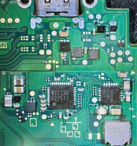
Can you post pics of the M92, BQ and fuel gauge areas of the board as you might be dealing with a charge related issue.
Just double checking but have you verified with a USBC breakout continuity from there to line destinations on the board and verified the USB fuse too?
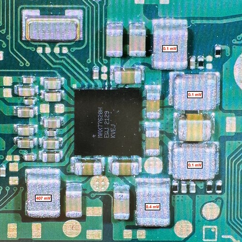
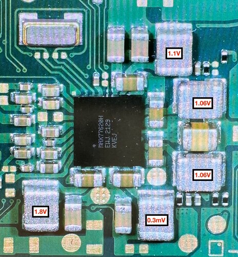
Also following promt to boot do you measure all rail voltages on the inductors surrounding the MAX77620H PMIC?
Also, can you let me know the current draw with a 5V USB too
Yes please keep me updated im getting 15v and .06 amps. Blacklight on and no display. Cant find any shorts the only one i see is around the 8316 ic. The only thing i did was replaced the lcd connector so idk if that area got shorted wheb the pins was missing. I got a thermal camera coming im see if i can inject some power and see whats going on i dont want to start replacing stuff i dont need. Lol im still learning too. I could of easily purchase another used switch but i rather buy the tools to learn how to fix it
I saw some on youtube write up a whole wiki of diagnostic on 1st boot 2nd boot voltage did you see that yet? And how to tell if the emcc is bad m92 p13
Sure thing, pictures are below.
I don’t have a USB-C breakout board, unfortunately. Just the USB voltage tester.
5V usb adapter without battery connected reads: 5.08V 0.02A and it cycles to 0A every 2-3 seconds.
OEM usb without battery connected reads: 15.3V 0.03A, no cycling.
Does the Switch Lite have the usb fuse? I’ve seen it on NS and OLED, but I don’t know where it is on the Lite. If it’s what I think it is, on the bottom side, closest to the USB port, directly next to the capacitor then I do have continuity through it.
What’s odd to me is that the USB draw as soon as I plug in starts at 15V. Doesn’t it, when normal and healthy, start at 5V and negotiate to 15V? I don’t see that happening as it is right now.
For measuring voltages around MAX77620H, do I check both sides of the inductors or does it matter? I’ve not done this yet.
IC Replacements Completed So Far:
M92 chip
backlight ic
8316 ic
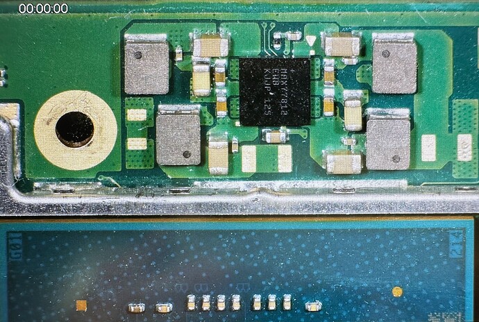
77812 ic
Can you let me know with the battery connected? (actually scratch this until the below issue is resolved)
Think you found it, ruled that out
Either side is fine, like with the 2R2 inductor, it’s just a copper winding underneath that ferrite material ![]()
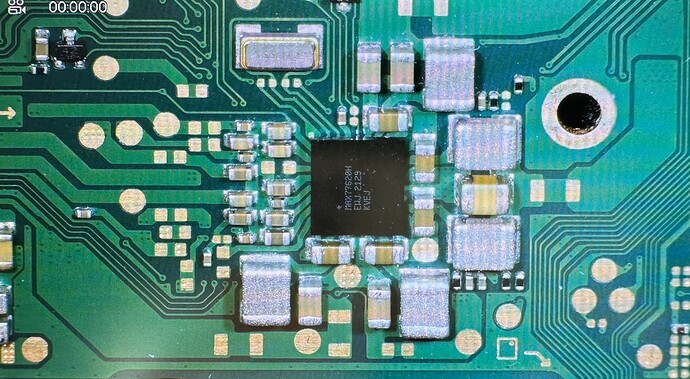
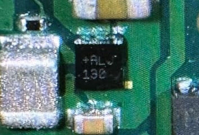
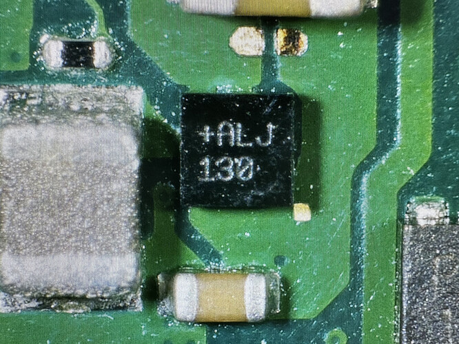
From your images, the only thing jumping out at me is this IC, almost looks like someone has planted this (squeezed it down, a no no) and/or without proper prep such as stencils, paste/balls. Though could be a trick of the light, have you mesed with this IC? Can you provide a better image.
Assuming this IC is at fault then this is likely your issue as it ties back to M92 and fets (assuming it’s the same on lites not double checked)
basically zero voltts which means it hasn’t responded to prompt / isn’t prompting to boot, presumably as a result of that IC i guess.
Ha, I noticed that IC as well in the pic and should have noted that it was a weird reflection from the light. Also my microscope is usually at a slight angle. I took a closer photo with the microscope straight up and down over the IC and it looks good to me. I also inspected it around at angles and didn’t see any solder blobs or anything that would make me think it got pressed down. What do you think?
I took a reading with the battery in and it’s the same, only the 0.2A is steady, no cycling.
ah, shame ![]() that would have been the smoking gun otherwise
that would have been the smoking gun otherwise
I take it it’s still basically zero volts at the inductors surrounding the PMIC? that is directly following plugging in the console to USB / pressing the power button / shorting relevant line to ground (I’m assuming you’ve tried both) if it’s just USB you’ve tried in order to prompt it to boot, try doing the power button etc and see if you get voltages at the PMIC inductors after and let me know
Oh and you’ll wanna keep battery plugged in throughout the above incase you have a bad / intermittent USB port
K, if you required the power button to get these voltages (ie, you weren’t getting them after usb prompt) then suggests you have USB related issues, maybe open lines or dodgy M92 / M92 support circuitry. Did you see current draw change after prompting with the button?
Additionaly your missing 1V35, this can be a variety of things, dodgy fuel gauge, EMMC issues, Audio IC and a whole heap of other things, could potentially even be the Max 77812 you replaced is dodgy (where dd you get this btw?)
I’d probably tackle the the USB related issues first by checking continuity with a USBC breakout board. then after If it were me i’d swp the fuel gauge out with a new one (from mouser or some other legit source) as it’s cheap and easy just to rule it out, then i’d move on to other things after
Alright, did some more testing and can confirm that pressing the power button does not give me those voltages. I might have been mixing up previous readings without the battery in or something, but I retested multiple times and those voltages, with the battery in, are present without pressing power.
I also had a spare USB connector and this one was dirtier than I liked so I went ahead and replaced it (this is a process I’m very comfortable with now). Solid connection on the new one and a nice fresh click when inserting the usb cable.
Anyhoo, no change in behavior. 15V 0.03A and no change in draw when pressing the power button.
To answer your questions, I buy most all of my Switch parts from AliExpress. Haven’t had a problem with anything yet, but I understand that’s a possibility.
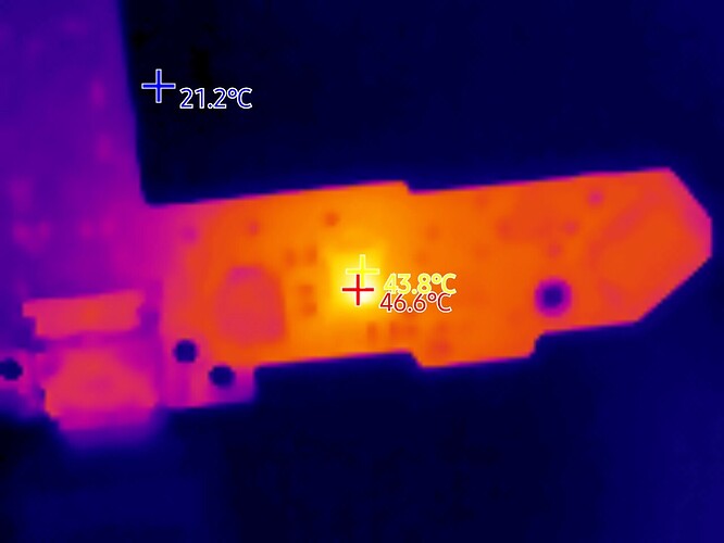
Hey man i definitely recommend getting a thermal cam if you can. Mine just came in i got a good price off amazon. Its usb c that connects to the phone. You also need a decent cam with good pixels that way you can see precise details. But i swear i check all over this board for any shorts and nothing. As soon as i plug in the thermal the bq chip was pretty hot no where else. Im going to replace it once i get some time hopefully that solves the charging issue im having
Do you happen to have the values for the usb test board? I just got 1 and want to make sure my usb is working correctly thank you
