so also some caps back of the board side b shorts. i am enject 3 volt put the under thermal camera . nothing getting hot. (all shorts coming only standby mode)
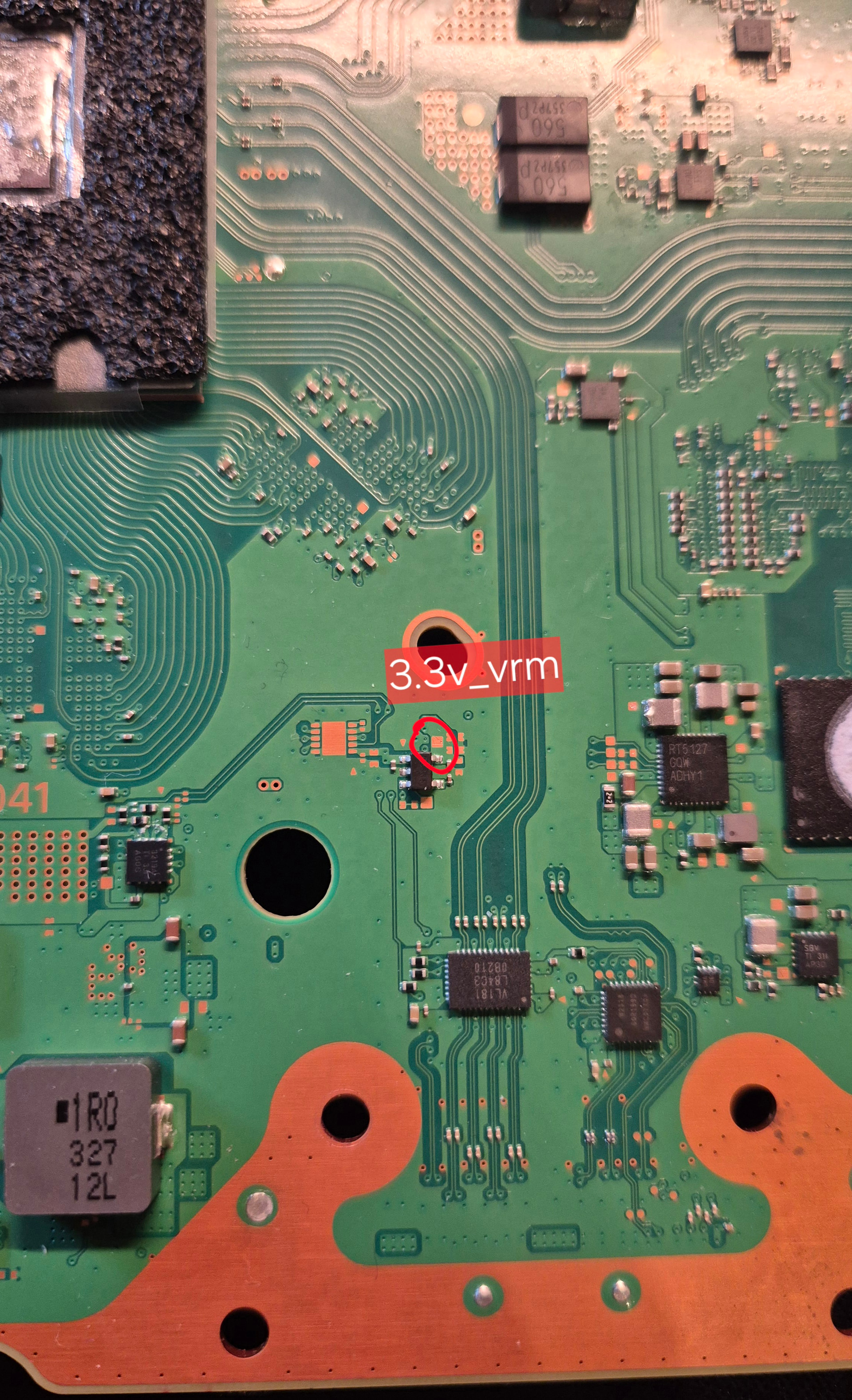
What about the 3.3V_VRM rail on pin 55 at the XPDE chip?
Please post a picture where you find the short and injected 3V.
If you still can’t post a picture, upload at an image hoster (_imgur.com/…) and share the link here.
pin 55 not coming 3.3v
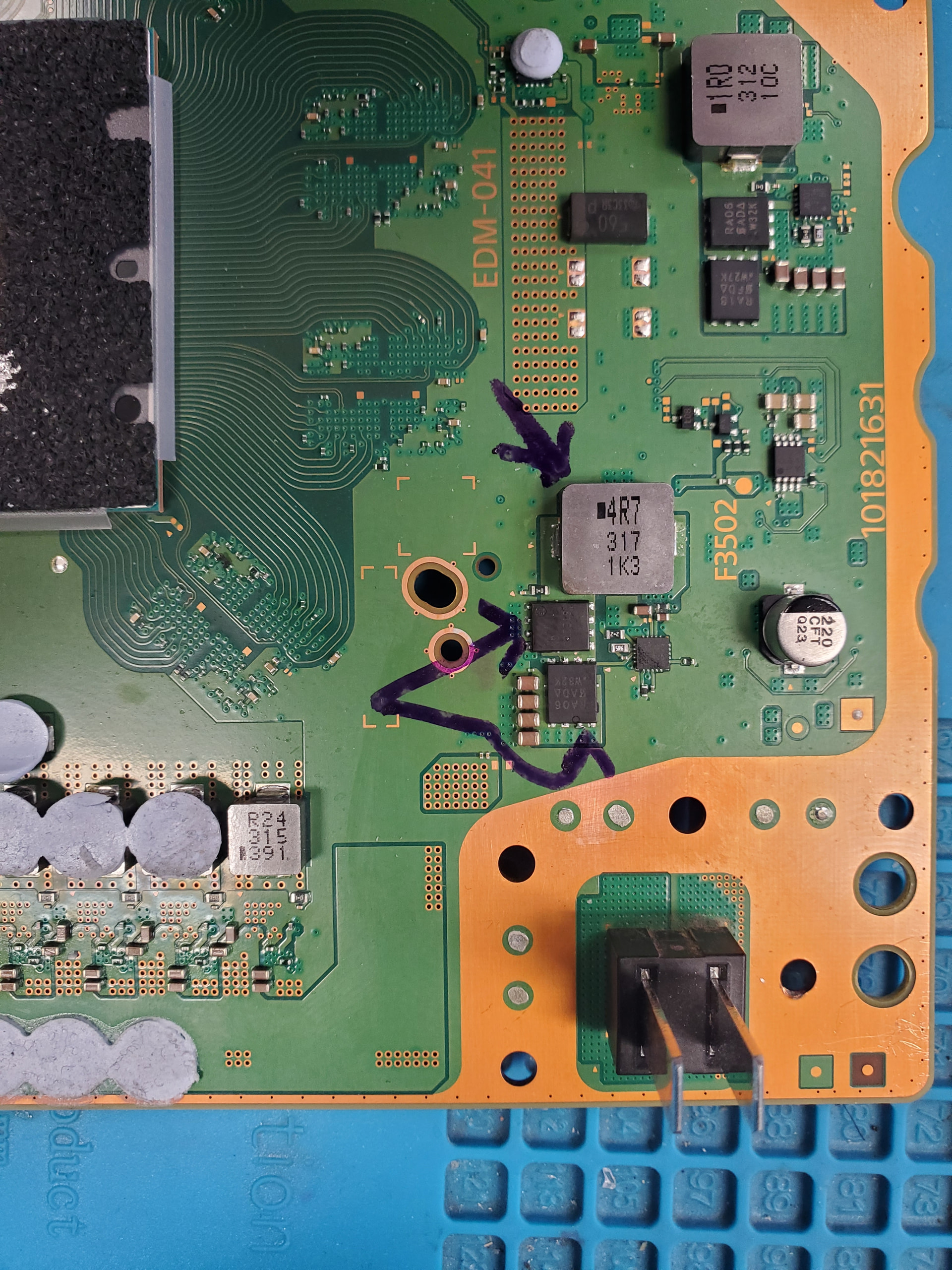
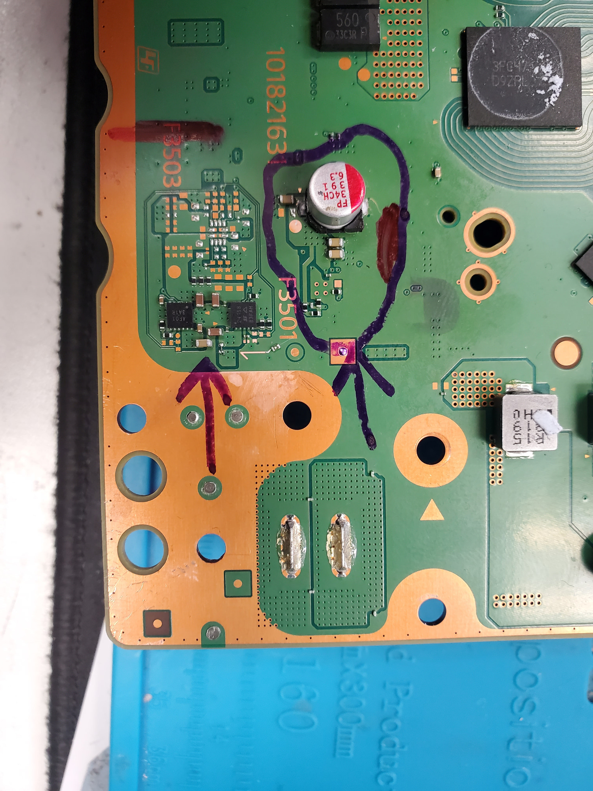
side A that 2 mosfets getting short.
side B i marked 2 arrow. in the circul all component geting short. and only one arrow it is shows one cap which is getting short. all off this getting short only standby mode.
This is not an issue.
It is not possible to check for shorts with standby voltages present.
Please check without any power connected the resistance to ground at pin 55 at the XDPE chip.
55 pin 0.4v without any connection. with stanby same voltage .
Same Problem with Uart Error “C00C0303 VRM controller access error”.
No Shorts on Standby Vorlage rails, all Stby Voltages are present. Power Draw stuck at ~30mA.
Maybe BIOS Problem? MBR2 Section showing “Different" in Wee-Tools and Console Service Tool Software. But i have no clue what this means. I have no idea how BIOS is working.
Anybodey with EDM-041 BIOS here maybe?
i have bios but it is dvd bios we need digital one because i have digital one
I need Disc BIOS für EDM-041.
PS5s should work without a disc drive connected.
Classic PS5 A version (BD version) will fail at update if any disc drive is not found.
The change in BIOS data only deactivates the check for presents of a disc drive, so the update will pass the disc drive check. Even with “changed to digital” will not deactivate the disc drive itself.
PS5 slims are build to attach and dettach disc drives. So it shouldn’t make a difference if the BIOS data is from a donor dump with or without a disc drive.
1 Like
Resistence on XDPE Pin 55 is 2,8k. Maybe XDPE can not be initialised because of BIOS hanging? Or it is the other way round? We will find out ![]()
At the edm-041 atm I can not find the source for the 3.3V_VRM.
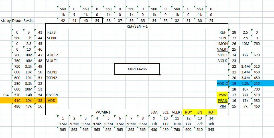
Here are my XDPE readings from a working edm-041 board.
The yellow marked are the lines to or from southbridge
1 Like
GUYS i have a lot of bios bins. how i can upload i dont know maybe i can send someone via email or something. or explane me how i can upload.
btw i wrote bios just now and it is doing same thing
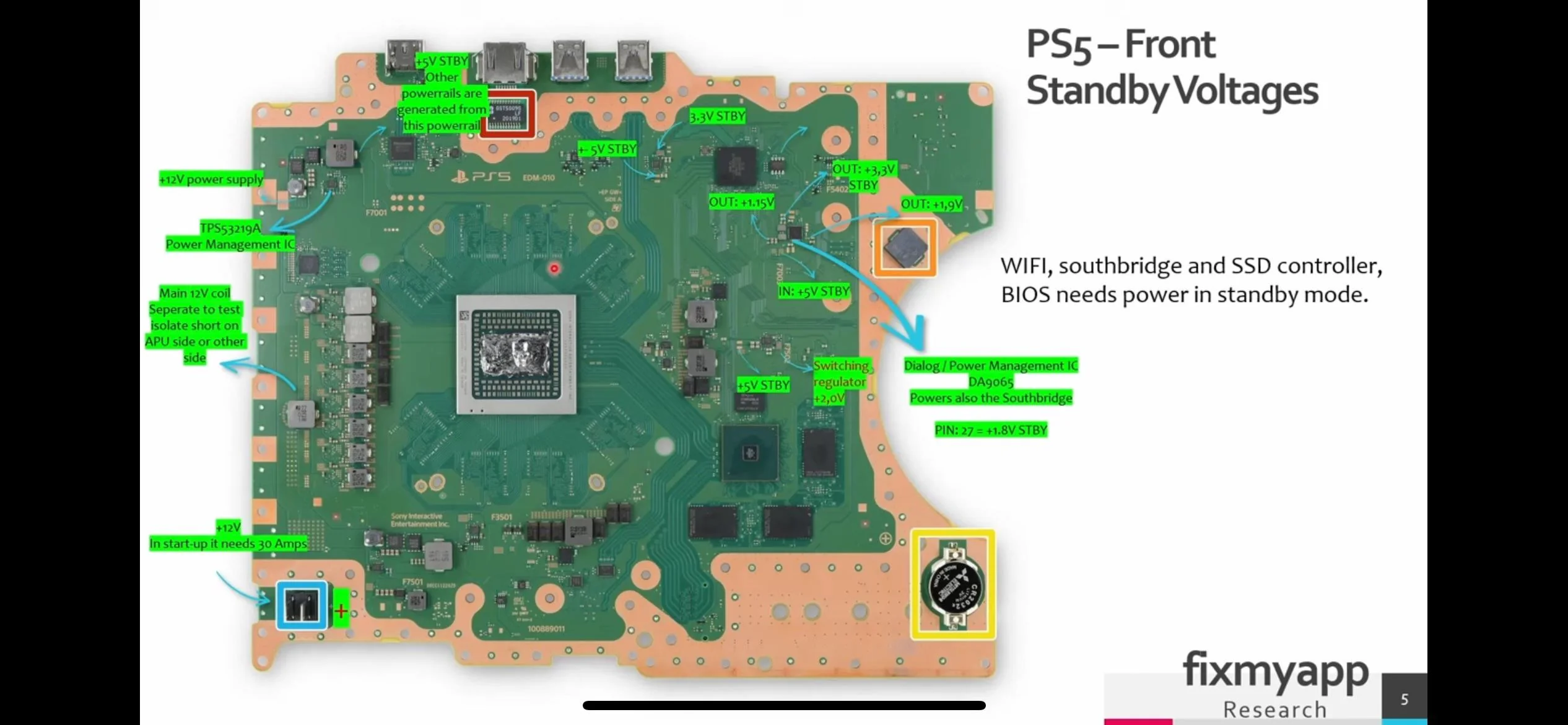
5v Standby on Pin 1 - Input on this Chip but no Output. Enable is missing. In need to figuer out where its coming from.
The EN for the 3.3V_VRM comes from the southbridge (PSW_MDCDC). But it is not present at standby. Only after start.
You can check if 3.3V are present at the 3.3V_VRM, if 3.3V are injected at pin 3 (CE) at the little LDO bug converter.
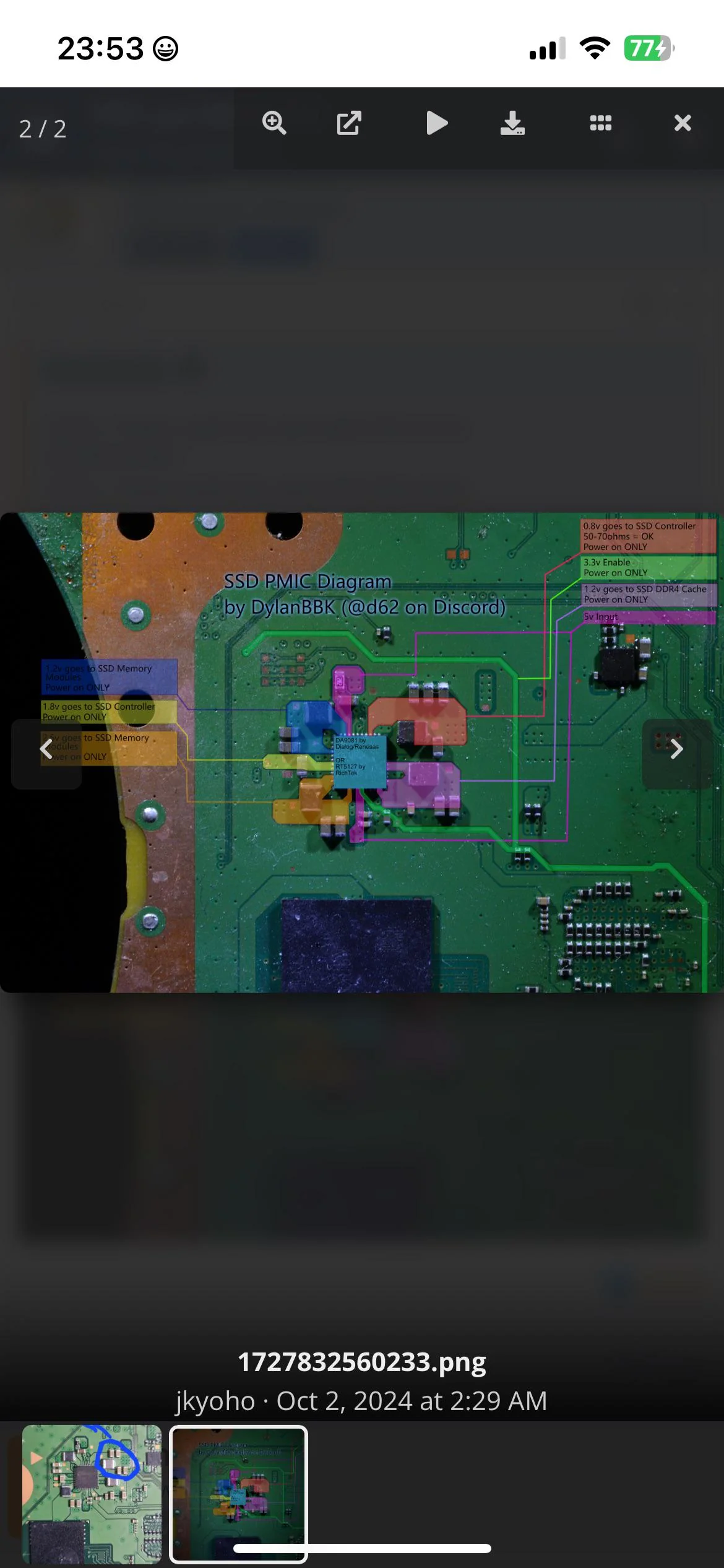
around my dialog ic when standby it is coming 3.3v and 5.1v but after that everything is shorting. i gonna share some schematics how it should be.