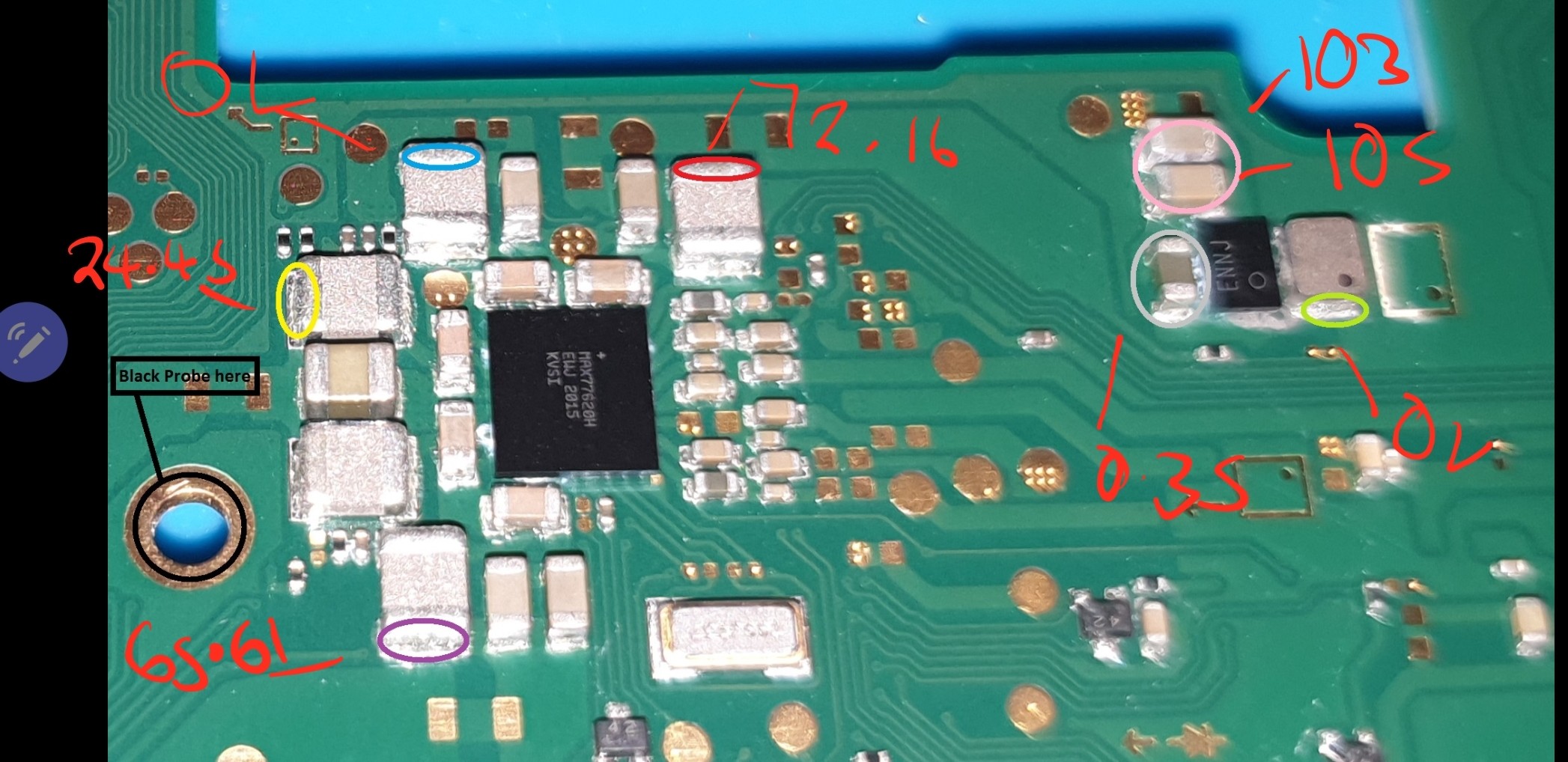
not yet, paste and stencil comes later when reballing the IC/s don’t worry about this for now, finding the culprit and clearing the shorts is the priority, don’t be thinking about putting these chips back on atm
You probably won’t find anything like this specifically for switch, but you might find some good info from ipad/iphone techs on yt, i believe paul daniels, sts, ipad rehab will have more than likely covered reballing at some stage.
When your removing either of these IC’s be sure they’re up to temp by giving them a nudge, they’re incredibly fragile so be gentle when grabbing with tweezers and lifting off.
Nah, leave them off. The touch up will effectively clean the area of corrosion, remove bridges (if there is any after lift) and to make it easier to wick/braid later on.
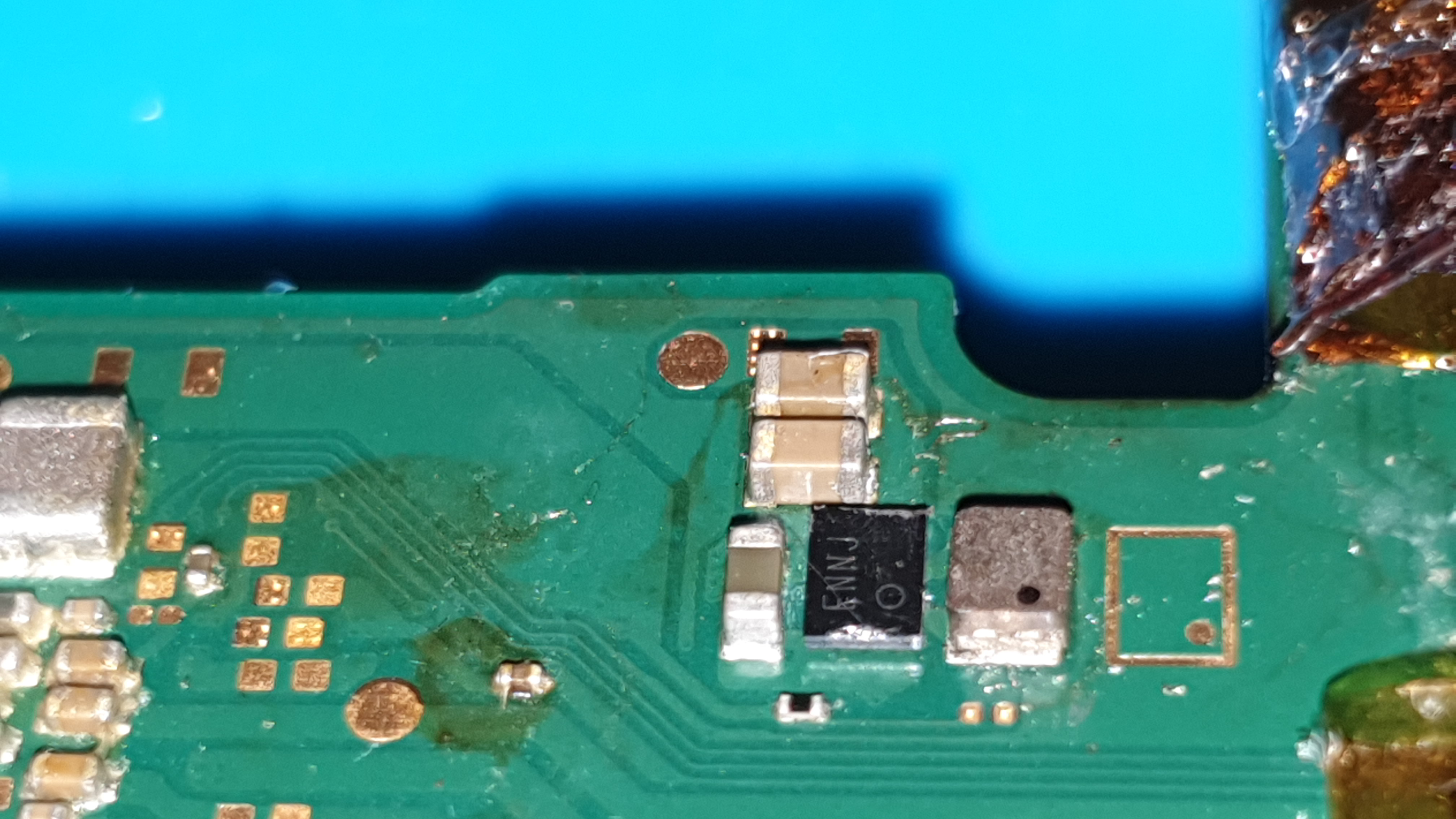
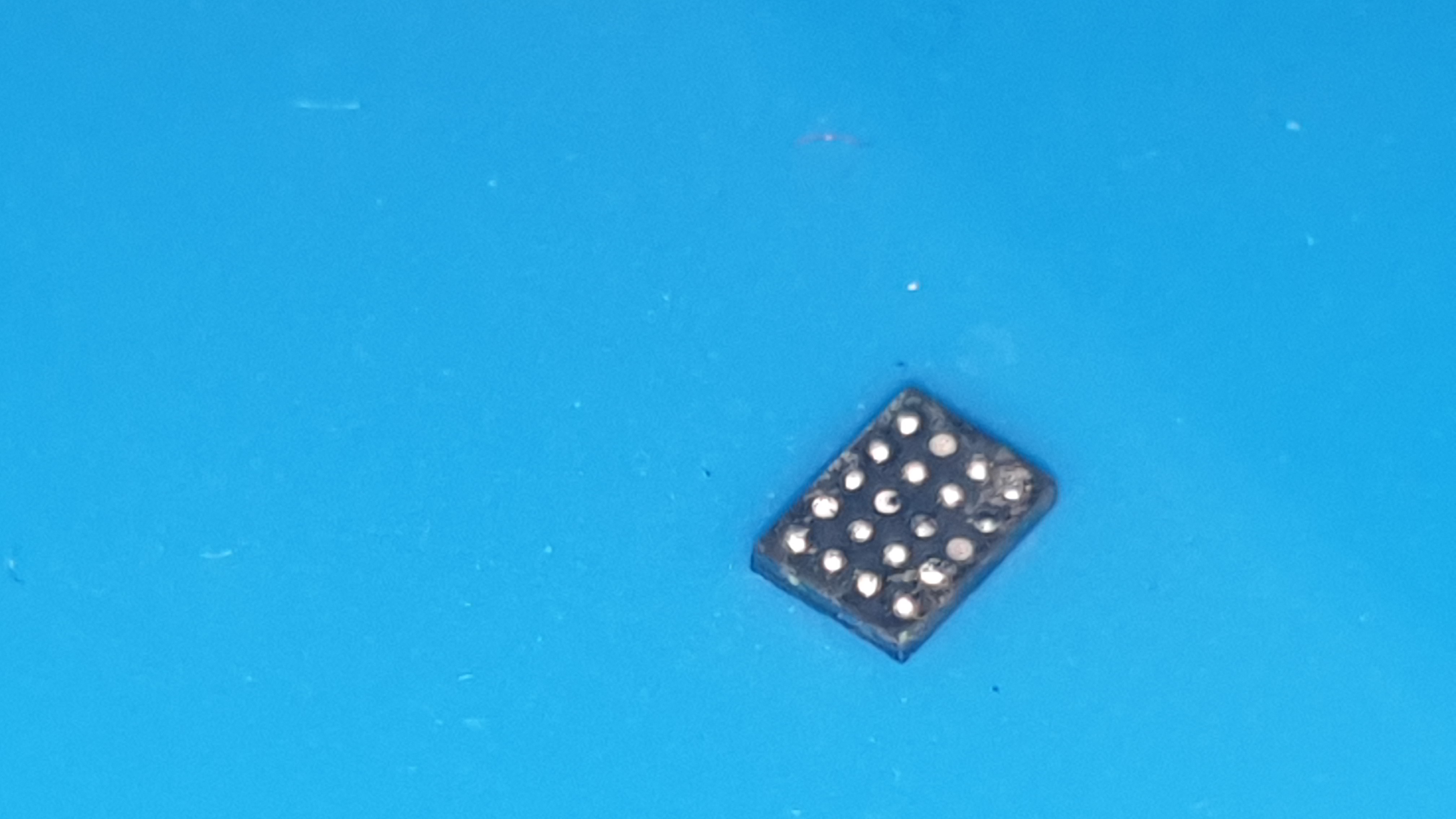
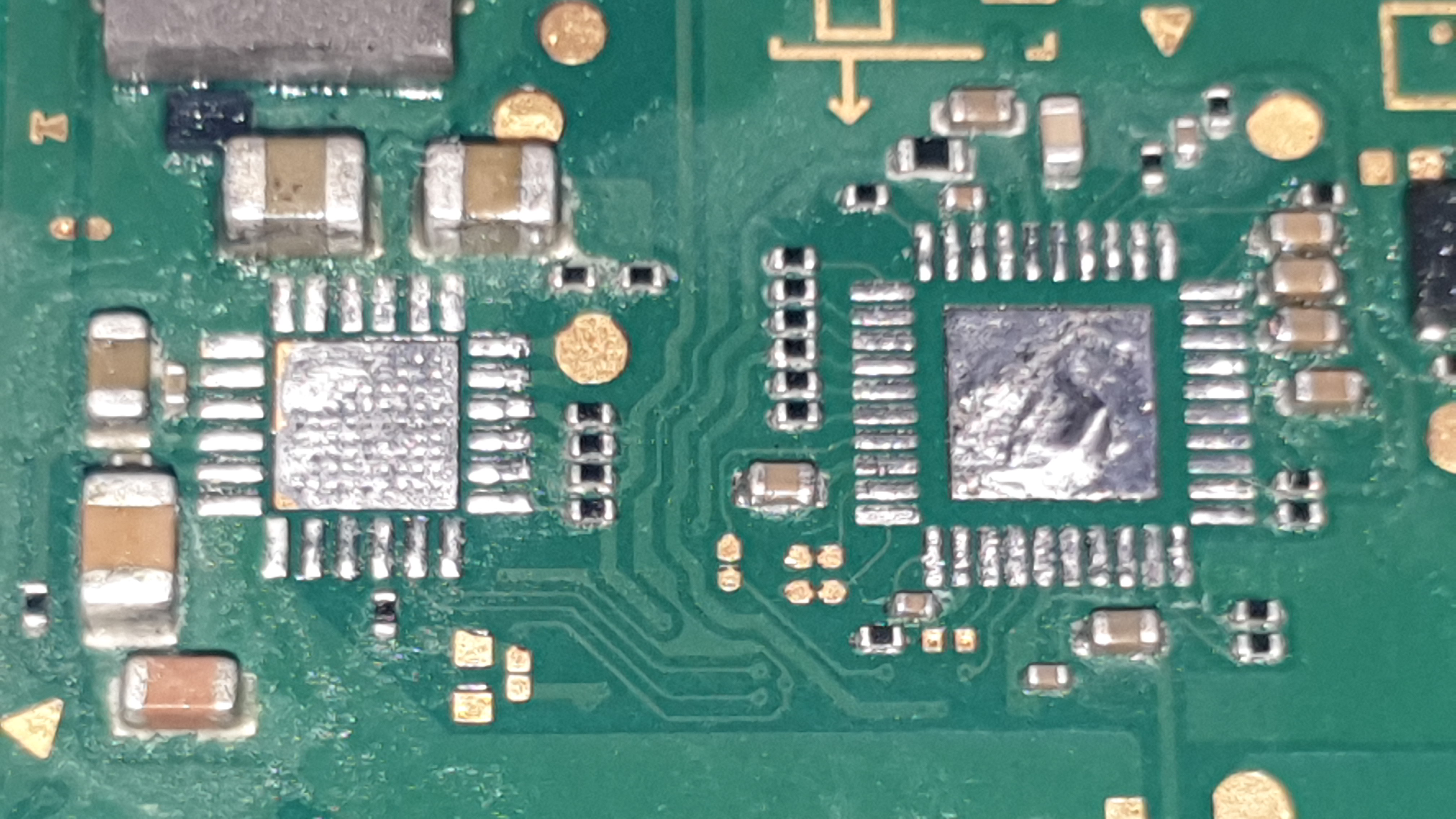
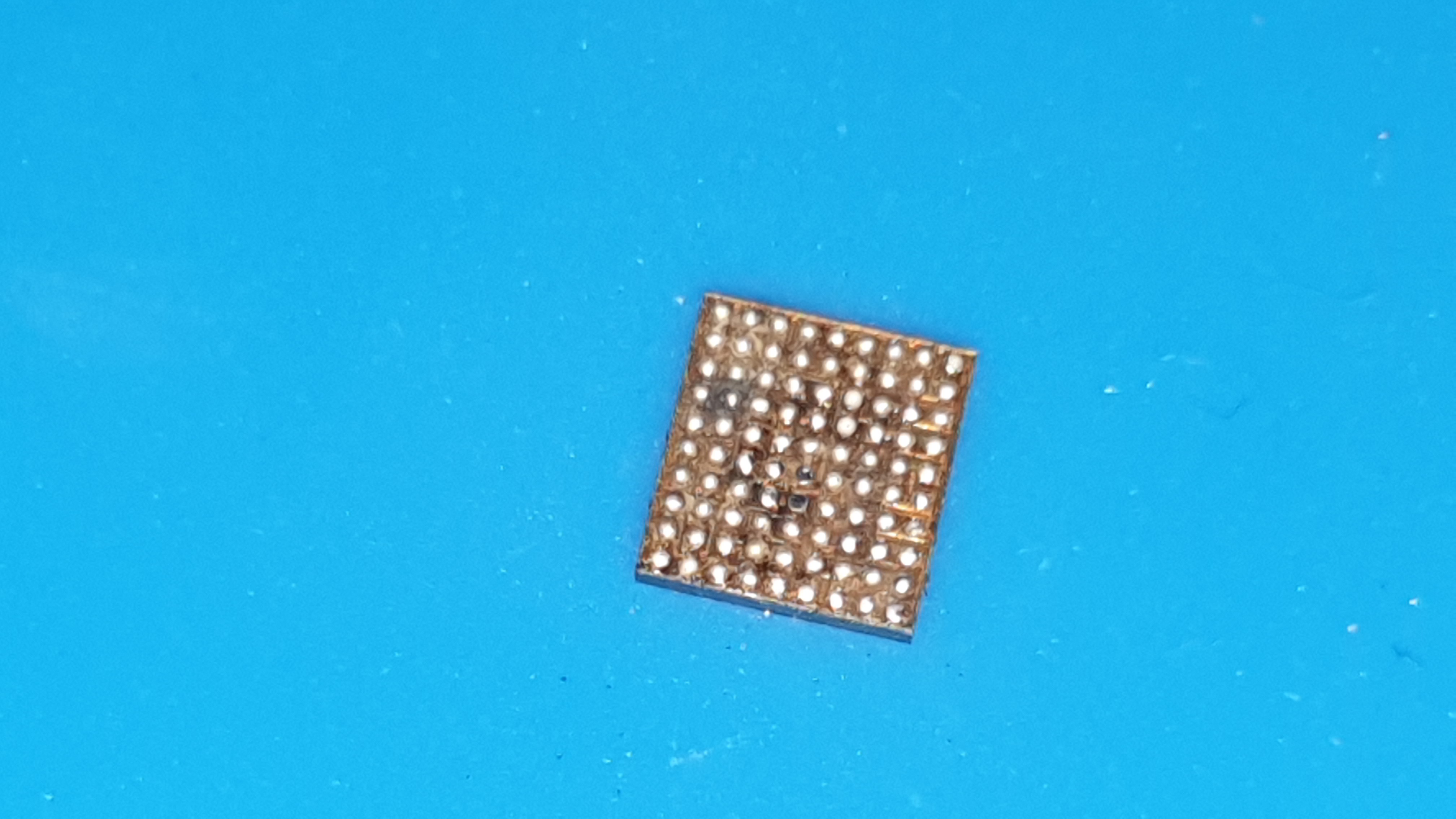
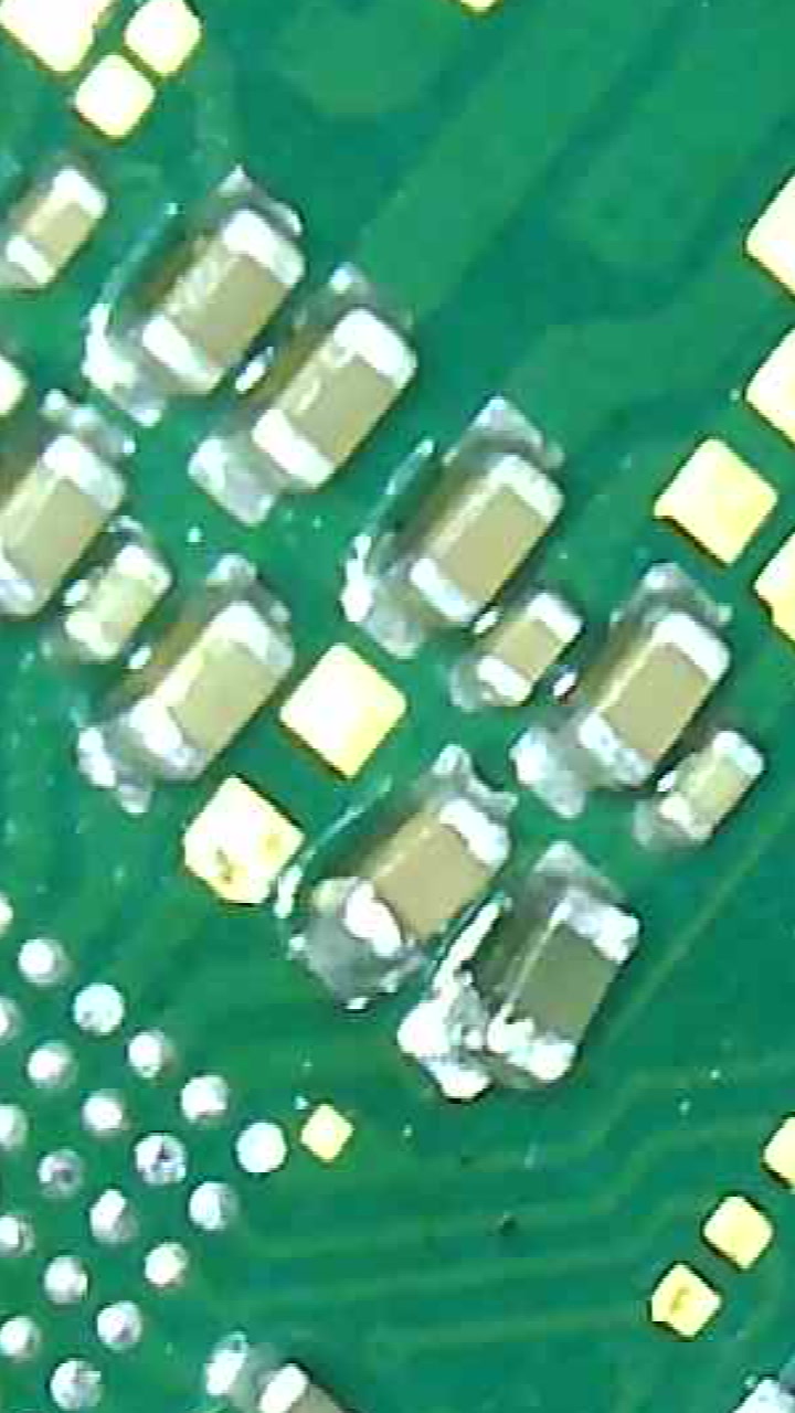
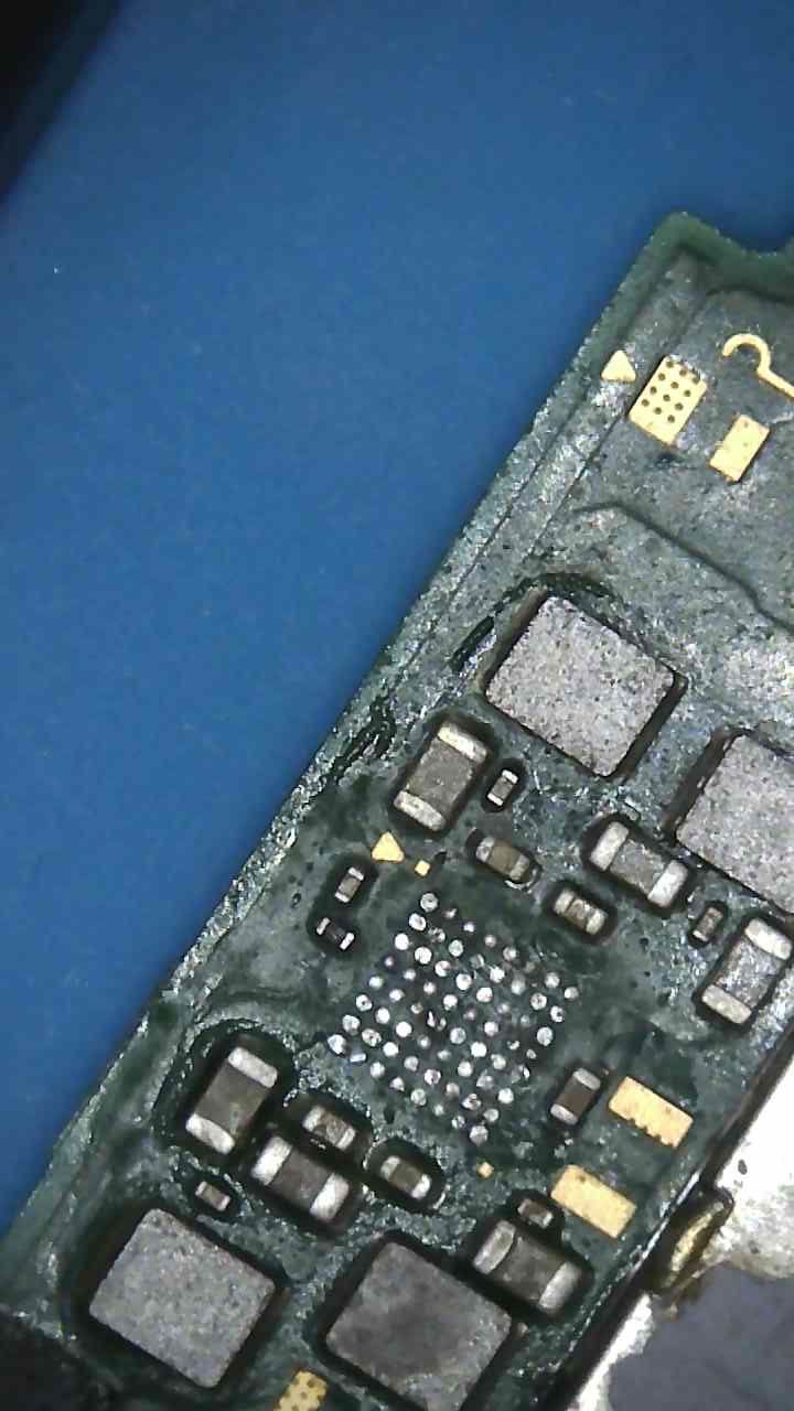
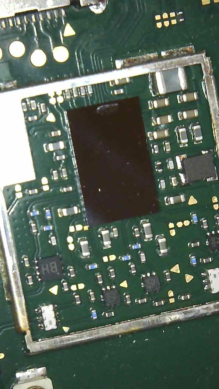
Unfortunately I haven’t been able to remove the smaller ic on the right. It’s very stubborn and it got to a point where I was concerned about damaging the board further. I was doing it for about 10 minutes. Even the cap on right budged and ic didn’t. I stopped when I saw the plastic edges started to peel. See pic. I tried your temps and mine and applied flux liberally whilst being careful with the ic. Not sure what to do.
While it’s possible the liquid/corrosion could be playing a part in this, it’s not recommended grabbing with tweezers and wiggling, as you increase the risk of pulling pads. Under normal circumstances, you should be able to give the IC/s a nudge with one side of your tweezers (gently) and if it moves it’s ready to be lifted.
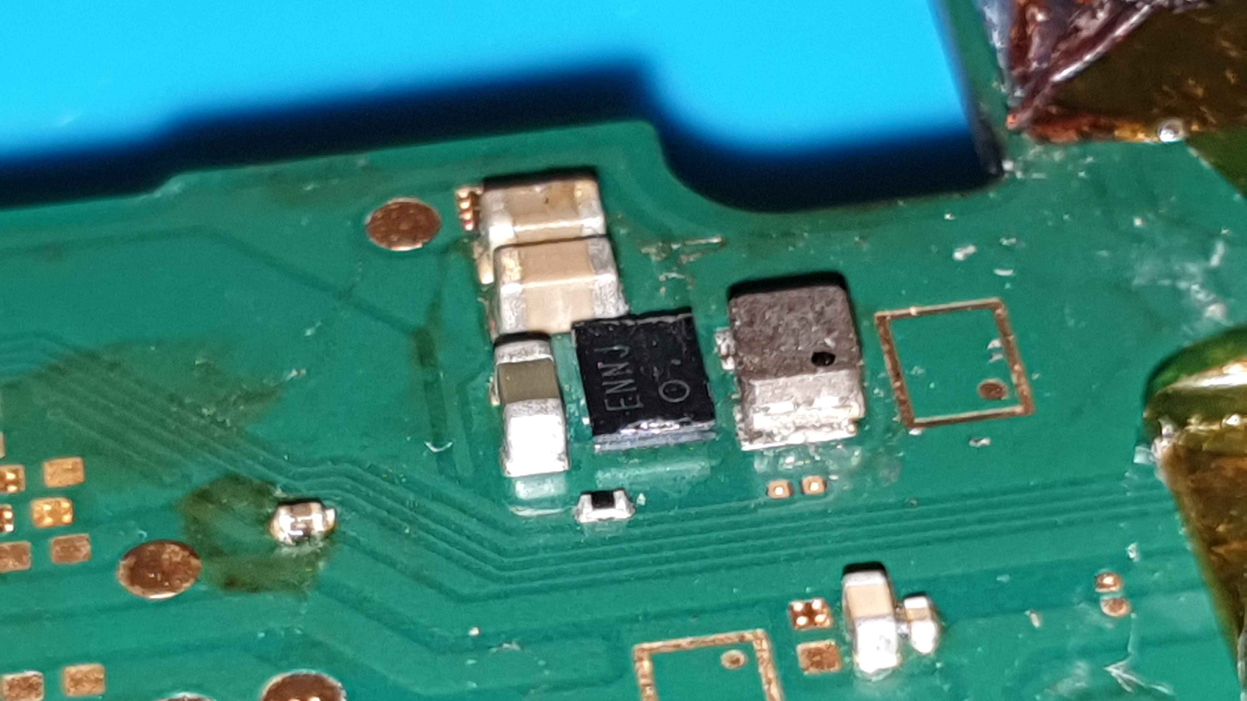
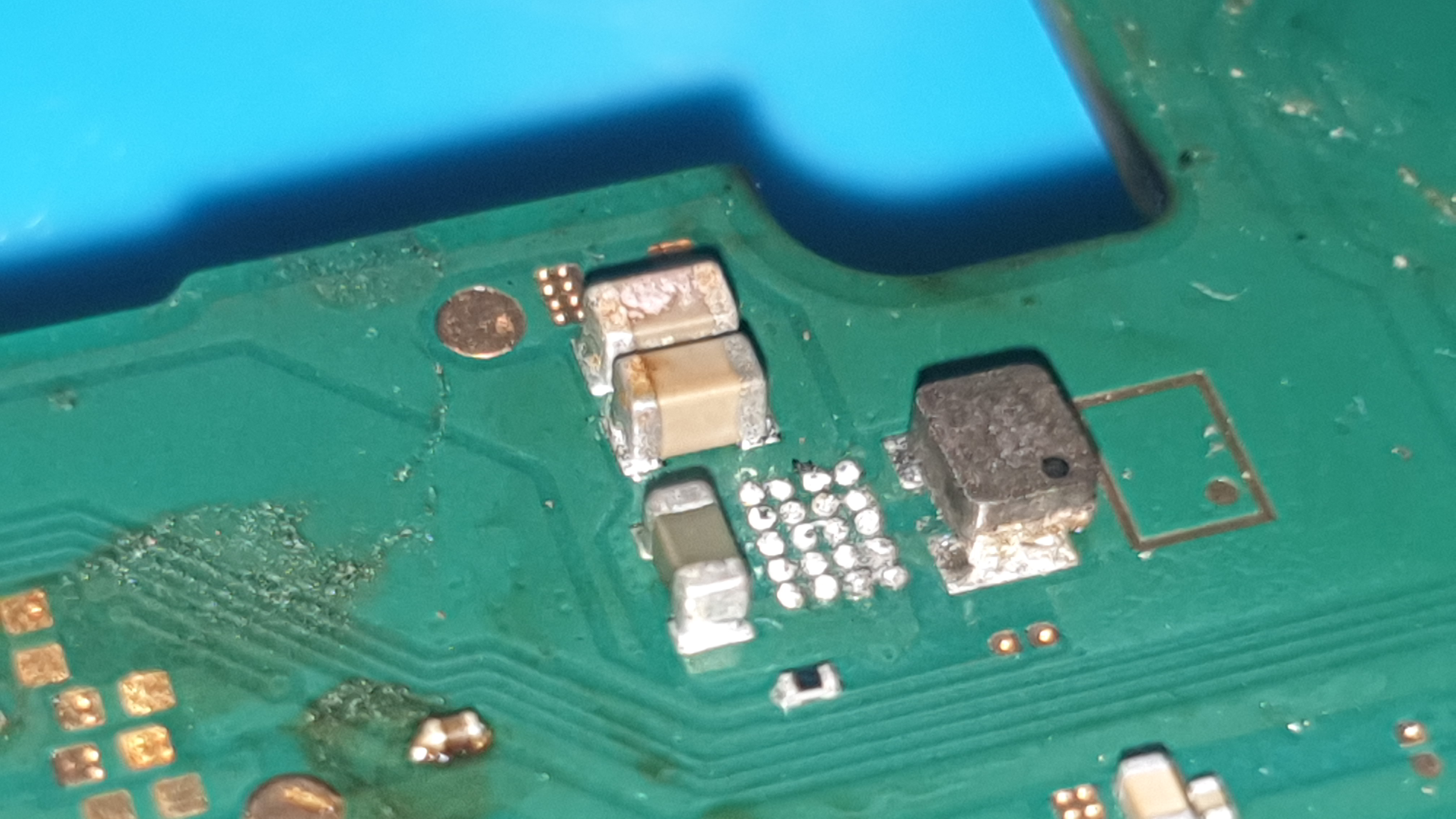
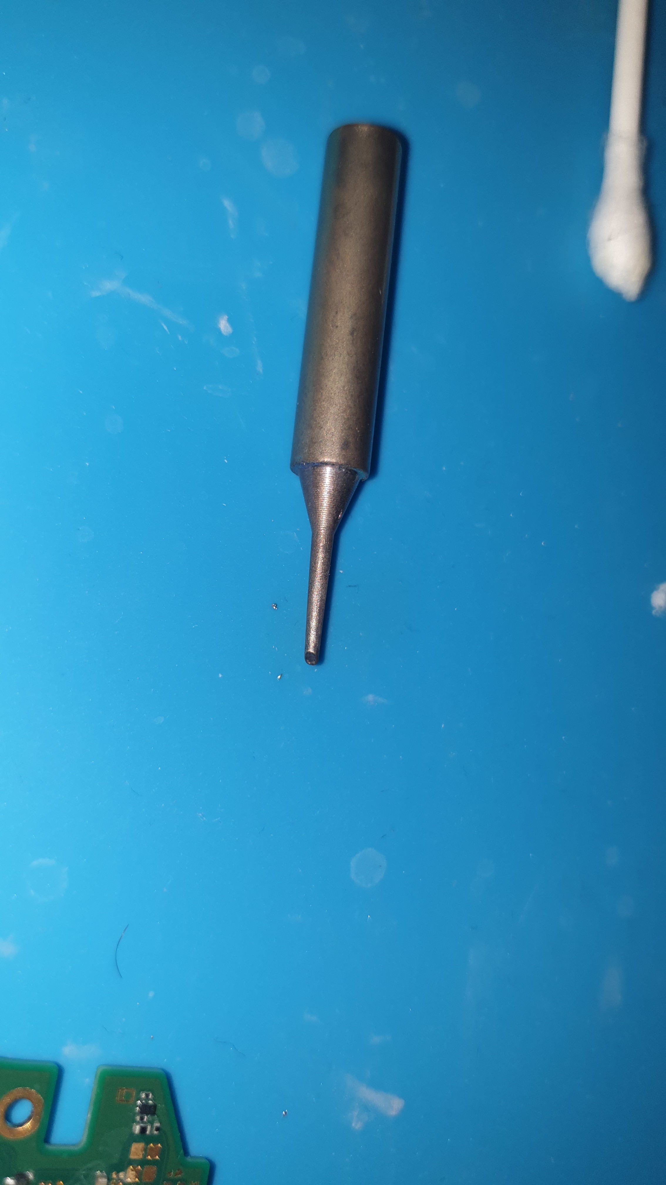
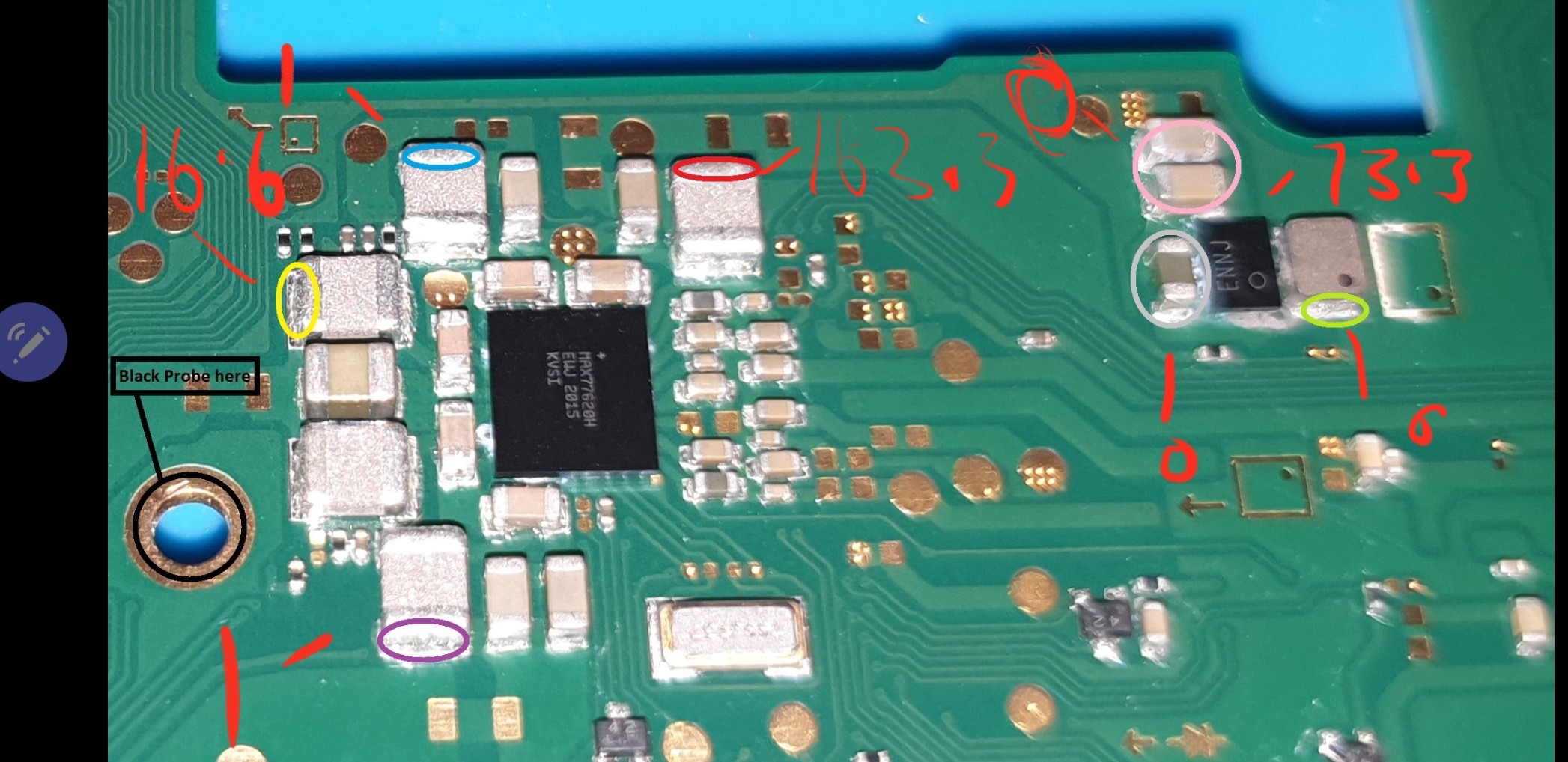
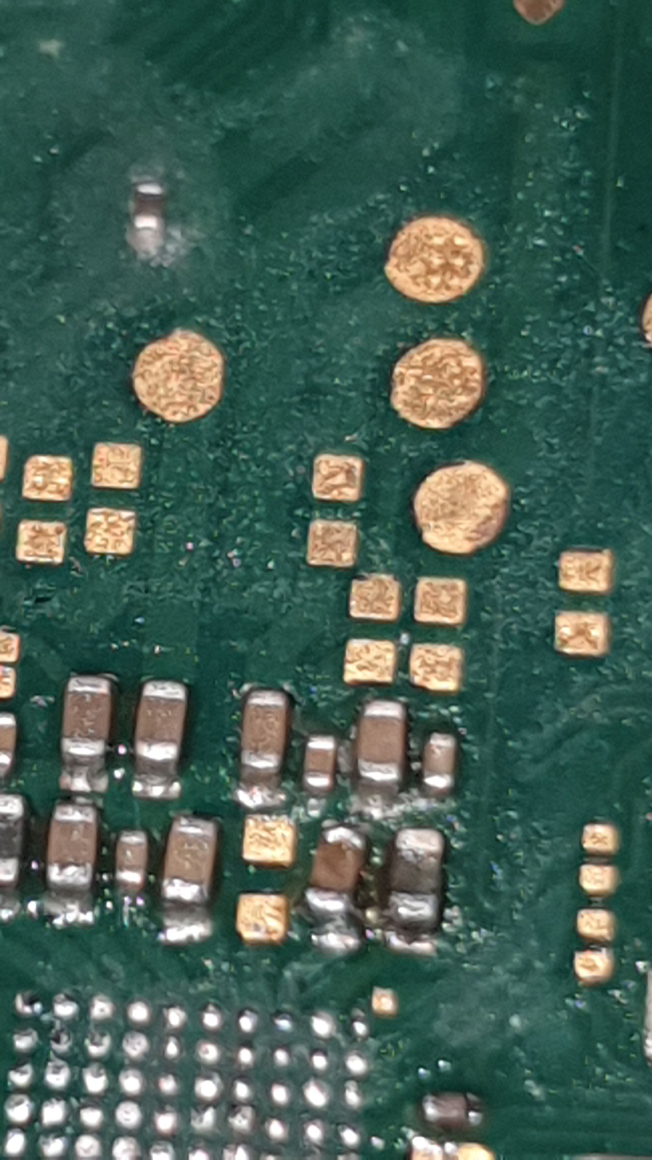
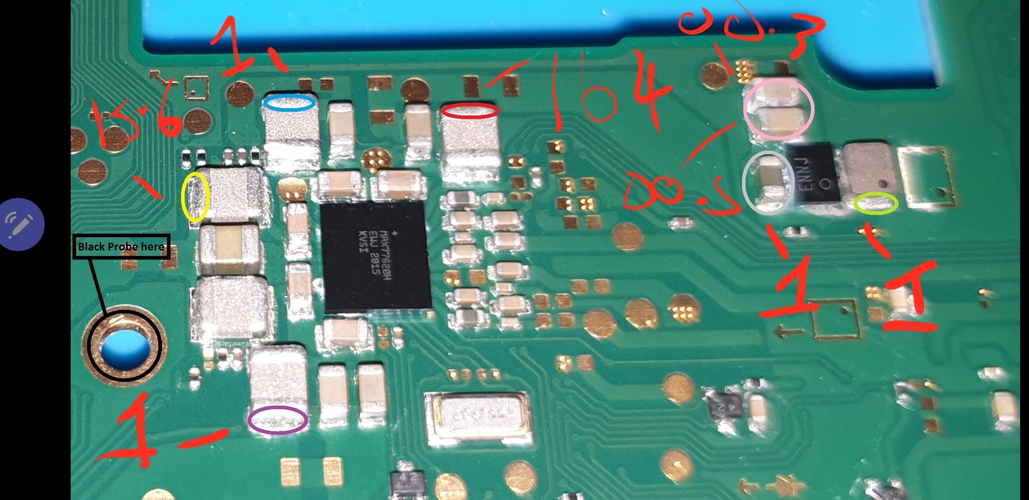
I can see from your image the pads on the board are still bridged, so your going to have to flux it up (liberal) and tin theses pads with leaded solder, I’m going to guess your soldering tip is going to be a nasty ol conical in which case you may have to heat that area of the board up with your hot air gun while your tinning with your iron in order to get the heat in. I can also see what looks like solder spatter on the caps (though it could just be the lighting) so you’ll have to clean them up also.
This is one of the reasons i don’t bother using it in these instances, it offers barely any protection and just creates a mess, the problems are worse with the cheaper knockoff versions as the glue isn’t silicone based and the residue is a pita
Yeah I tried to be careful as possible but this IC was different from the other two (BQ/M92). So much harder and that’s possibly due to the corrosion.
What do you mean by conical tip? tbh I am thinking of getting a proper solder station. Whilst the hot air is gun is not bad the solder gun and tips aren’t great but after a few attempt I have managed to get rid of the bridge : )
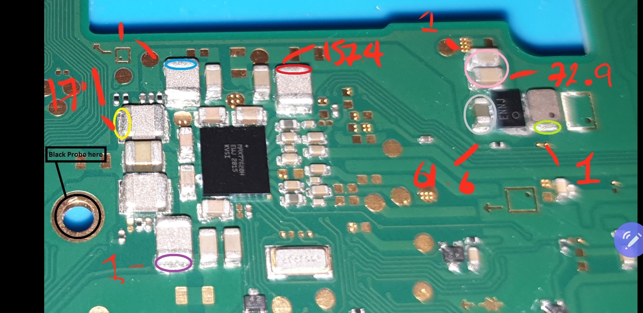
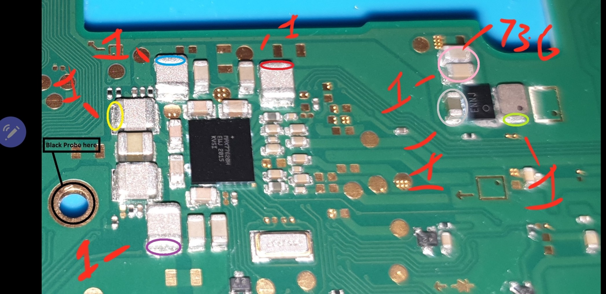
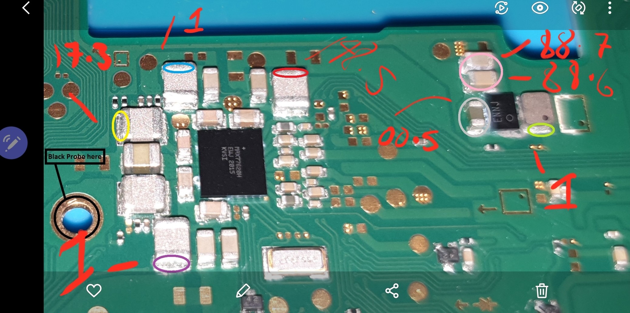
Took the readings again. Slightly different but even when am getting am number greater than 1 the mutlimeter numbers are moving widely unless I hold down supet still.
no, as the rails which are shorted are pointing at the main PMIC, though thats not to say it’s the other IC which is responsible for this (due to VIN short) but it’s less likely
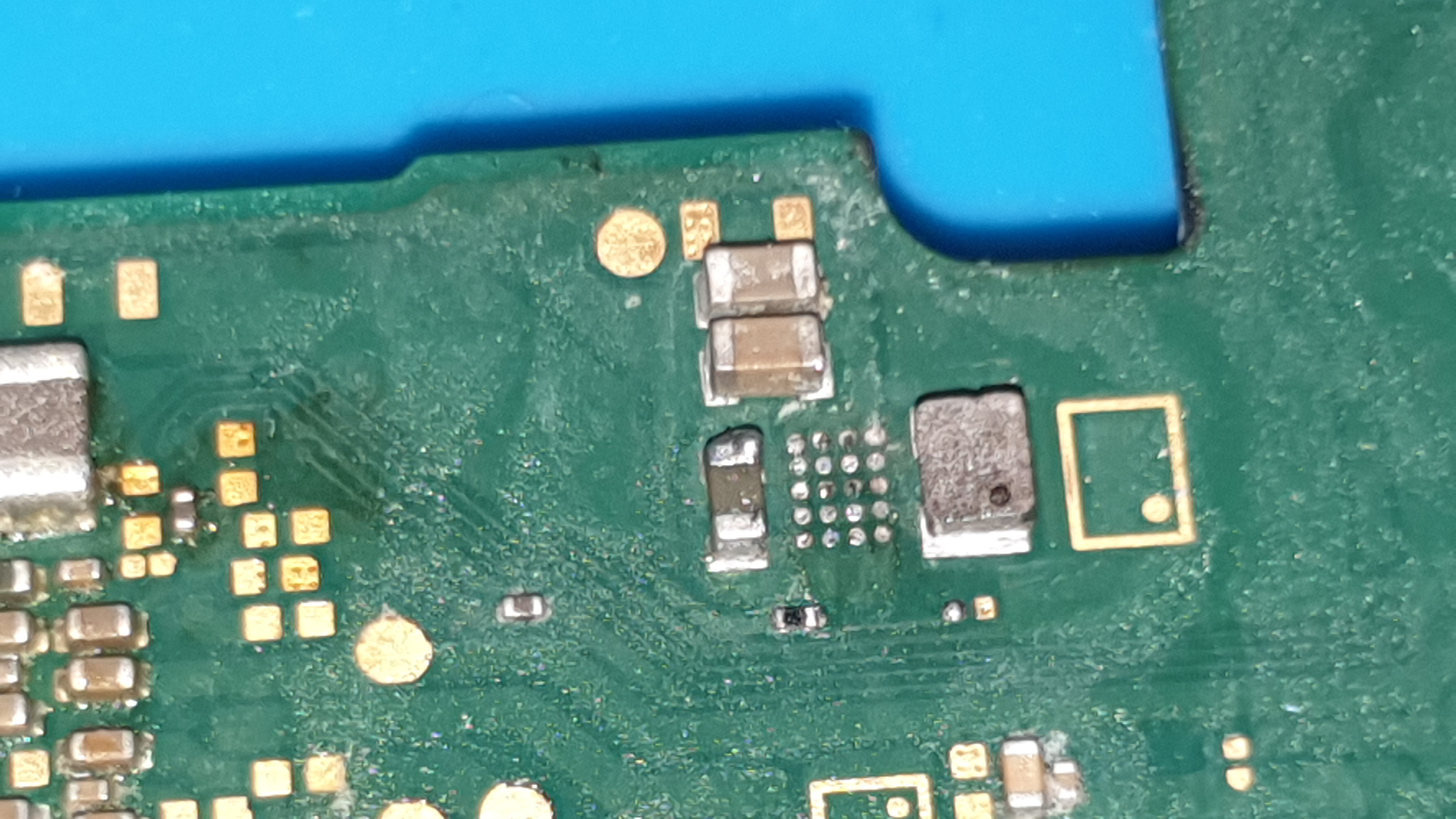
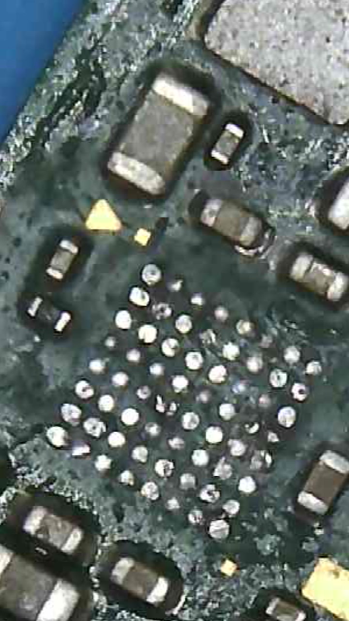
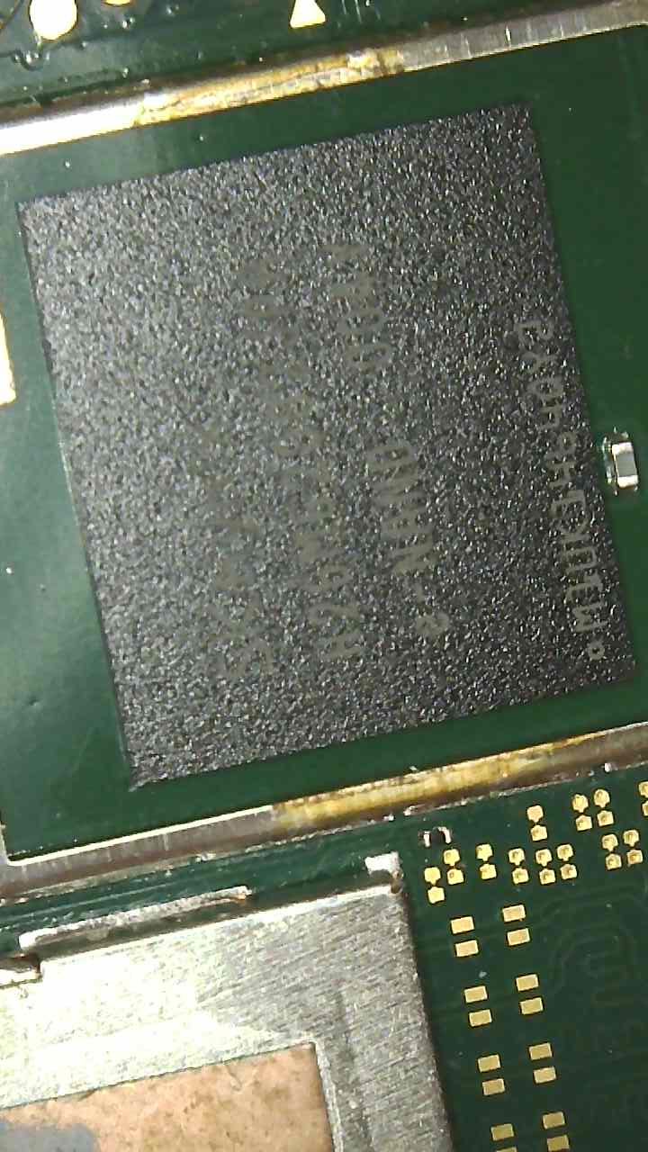
Ok managed to take this off more easily.
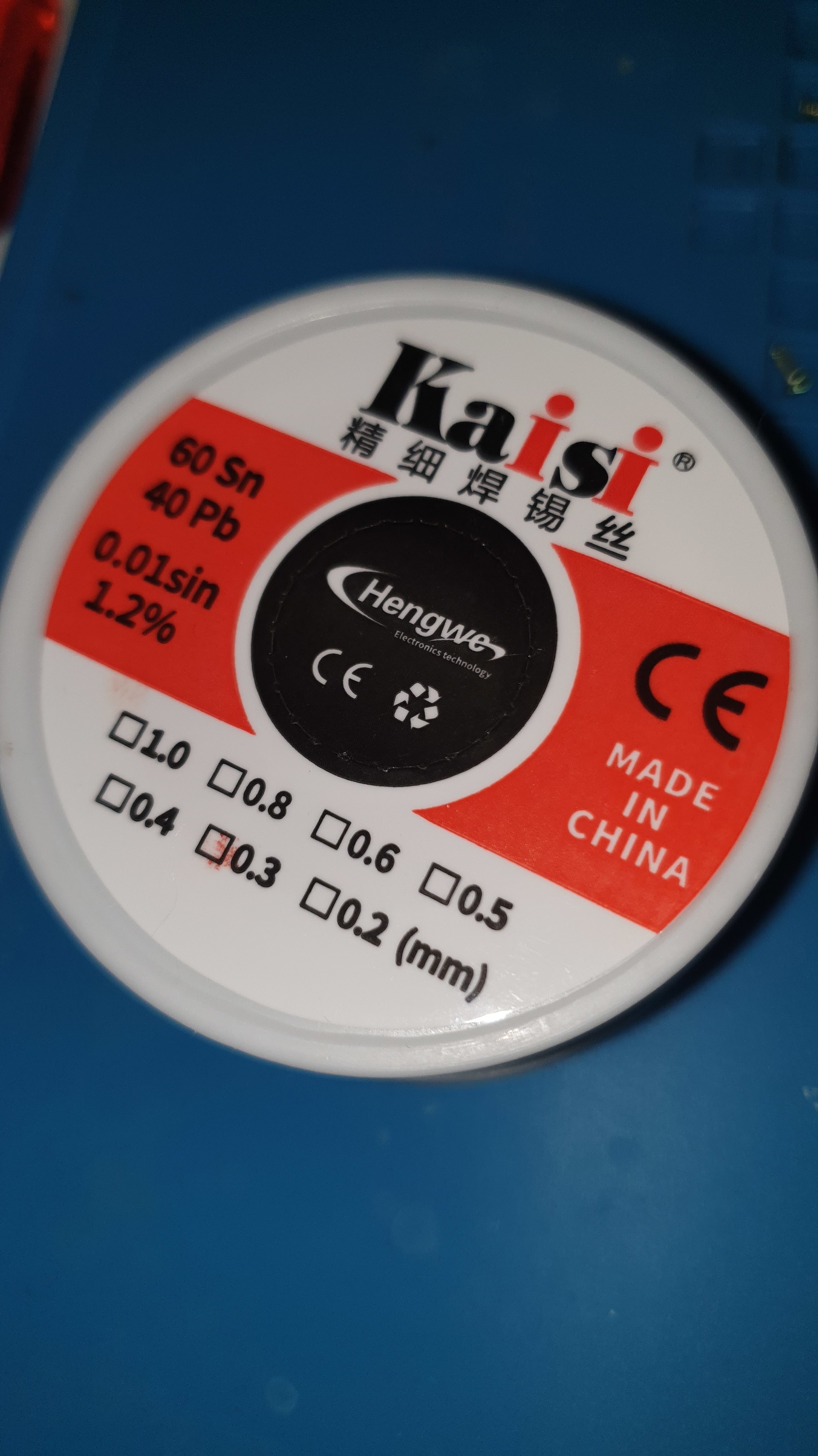
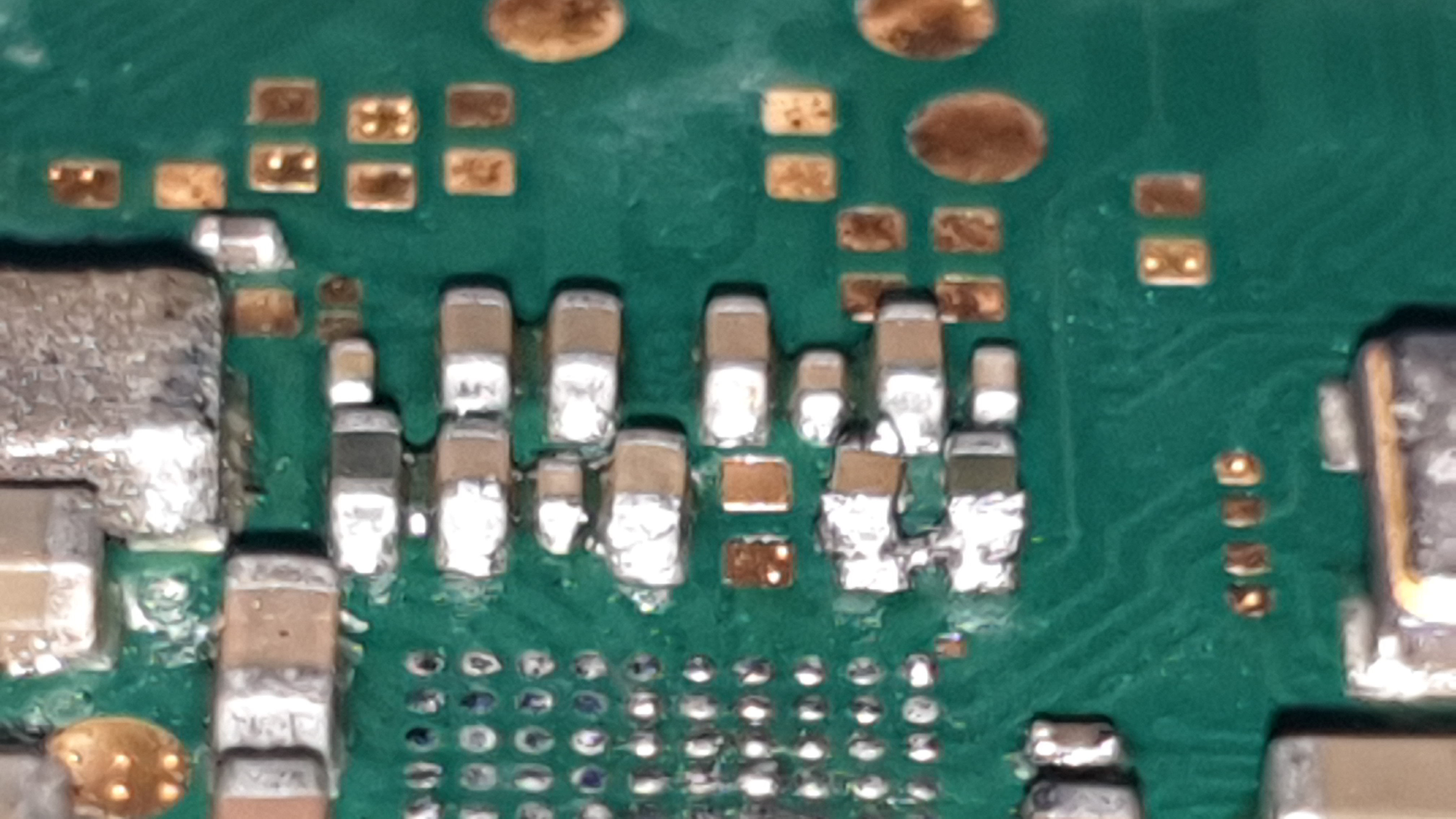
But I created of a bridge on two caps. And had I done research on leaded solder I wouldn’t bought this rubbish Kaisi stuff. I will have to order new leaded solder and figure how to unbrigde it. Try flux and desoldering wire but it’s hard to get rid of it.
So far readings haven’t changed but I will need to fix the bridge before anything.
In order to fix the bridge, switch your iron tip over to you biggest, flux heavily, touch bridge then dab tip to clean in wire ball, clean rinse repeat with flux until the majority has gone, flux it up again and then you could just hit it with the hot air again and they should fall back into place.
Alternatively, You can set your hot air to about 200c and hover it over this area while your clearing the bridges with your iron, i suspect your iron/tip is struggling with the thermal mass and the hot air will help
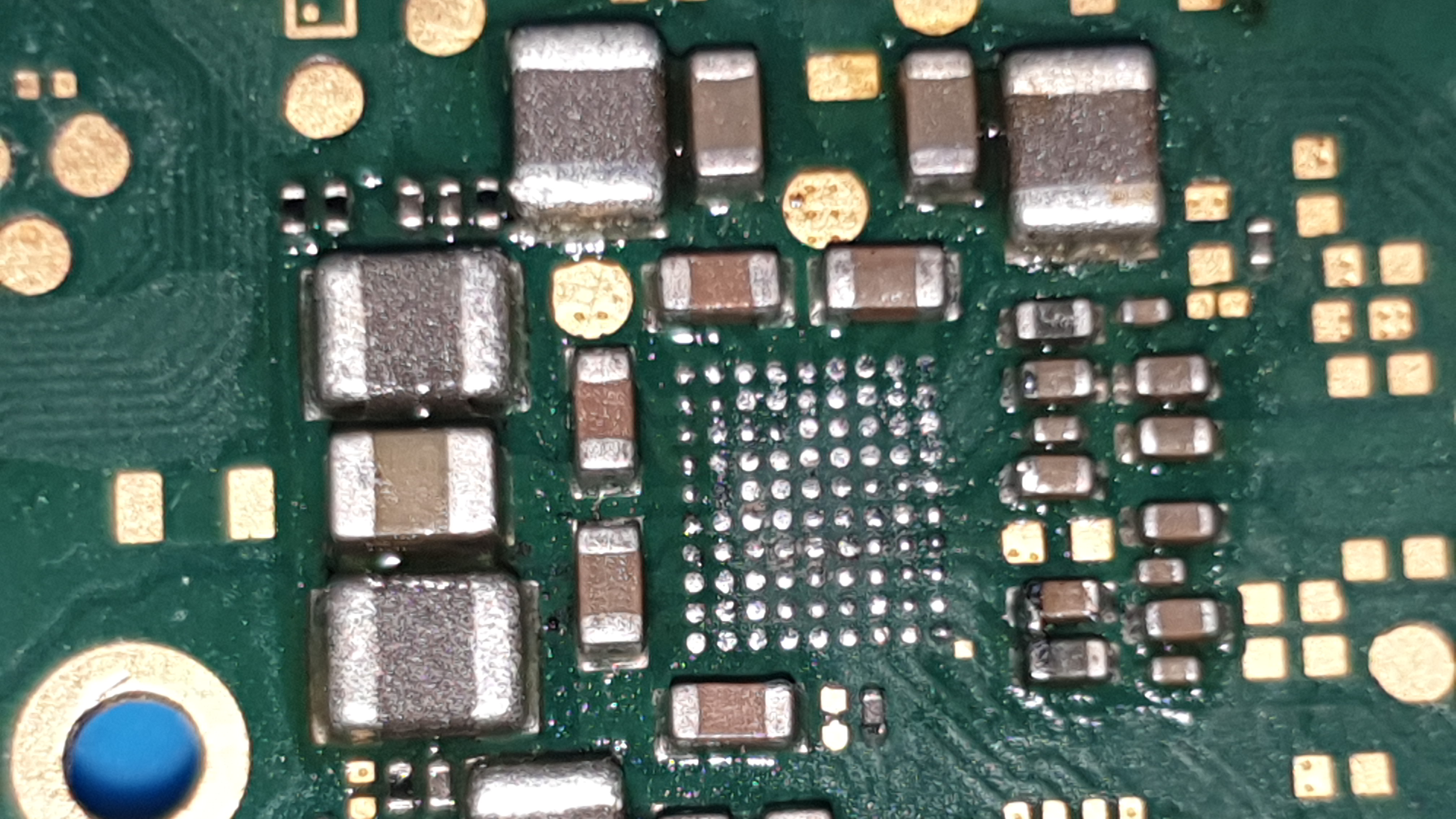
Afterwards give thiese areas a good scrub with touthbrush and IPA
Purple has a reading now but bad to hold still due to fluctuations.
Green still 0L i did get readings before but I knocked out of place and put it back nothing on both meters. It does try auto range but then settles on 0L