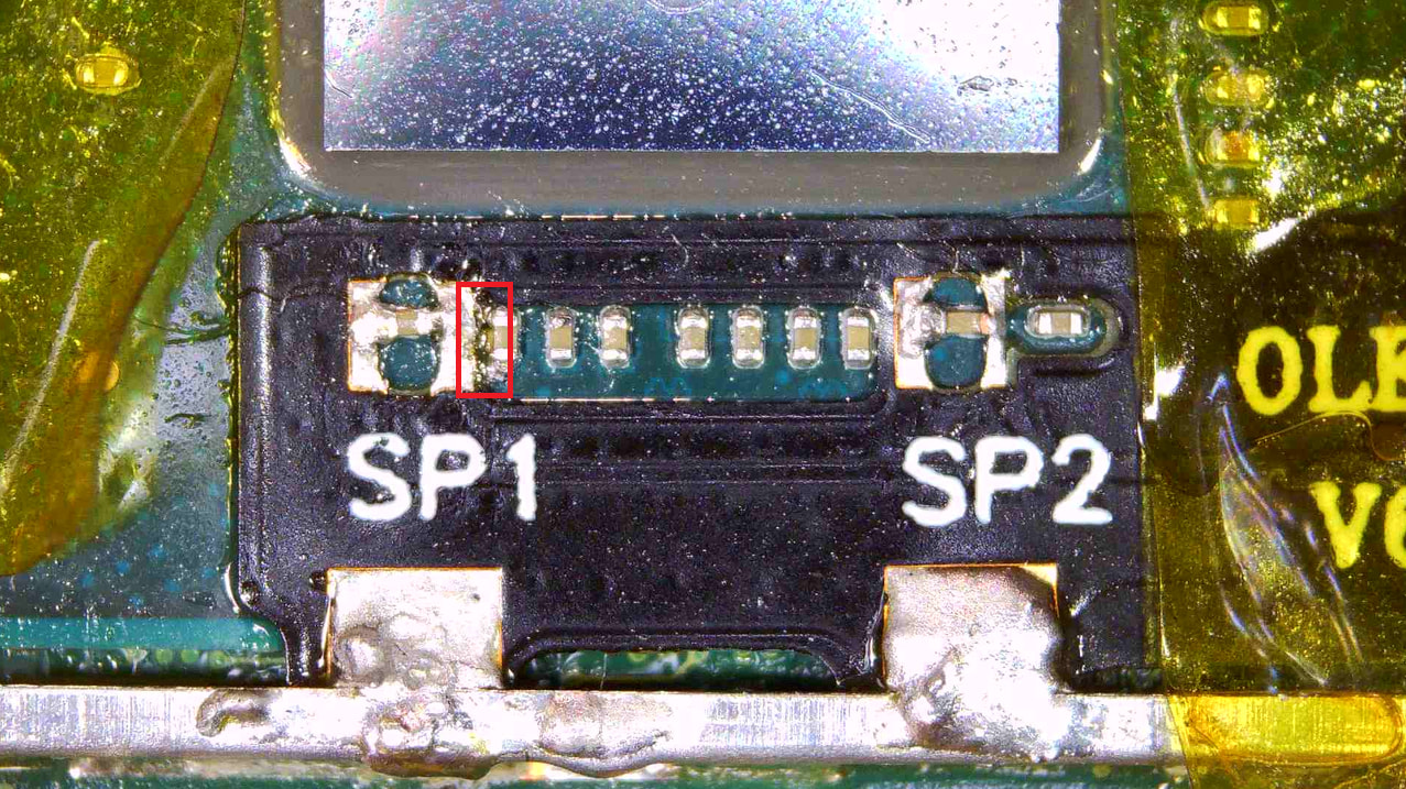
Hi everyone, first time poster, long time trouble finder. So trying to mod a v2 Nintendo Switch 1. Added the ribbon cable per what I’ve seen but might have gotten myself into trouble again. So dropped too much solder on one of the joints which ended up covering the capacity next to it. Used desoldering wick to get as much as I could up, but the board doesn’t seem to be turning on. I replaced the digitizer on the front also because it was in rough shape, well putting it all together the screen doesn’t show. I tried installing it with the picofly v6s oled mod chip installed. Now something I’m trying to figure out though is these resistors on both sides seem to goto ground and i don’t know if that’s normal… I’ve thought maybe it’s the a short near the sp1, but i get continuity on both sides of the resistors up to the resistor just past SP2 on the far right.
Checking the resistors on the side where the emmc chips are, those go to ground on only one side of the resistors. The side closest to the emmc chips. So how boned am I?
Plugging in the board, it gives 15v, 0.7w @ 0.04A without the battery, but when i plug the battery in it changes to 7.2W which i’m assuming means at least the charging circuit still works, but no fan spin and no lcd when i hit the power button.
https://drive.proton.me/urls/9NASSS6HCM#tDcJVbEBE6Ek