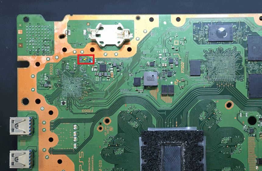
I’m troubleshooting a PS5 Fat with an EDM-033 motherboard. It does not turn on or emit any beep when pressing the power button.
In UART Monitor Mode, the console continuously outputs:
$$ [MANU] [ACINDET] AC IN DETECT Low:A7
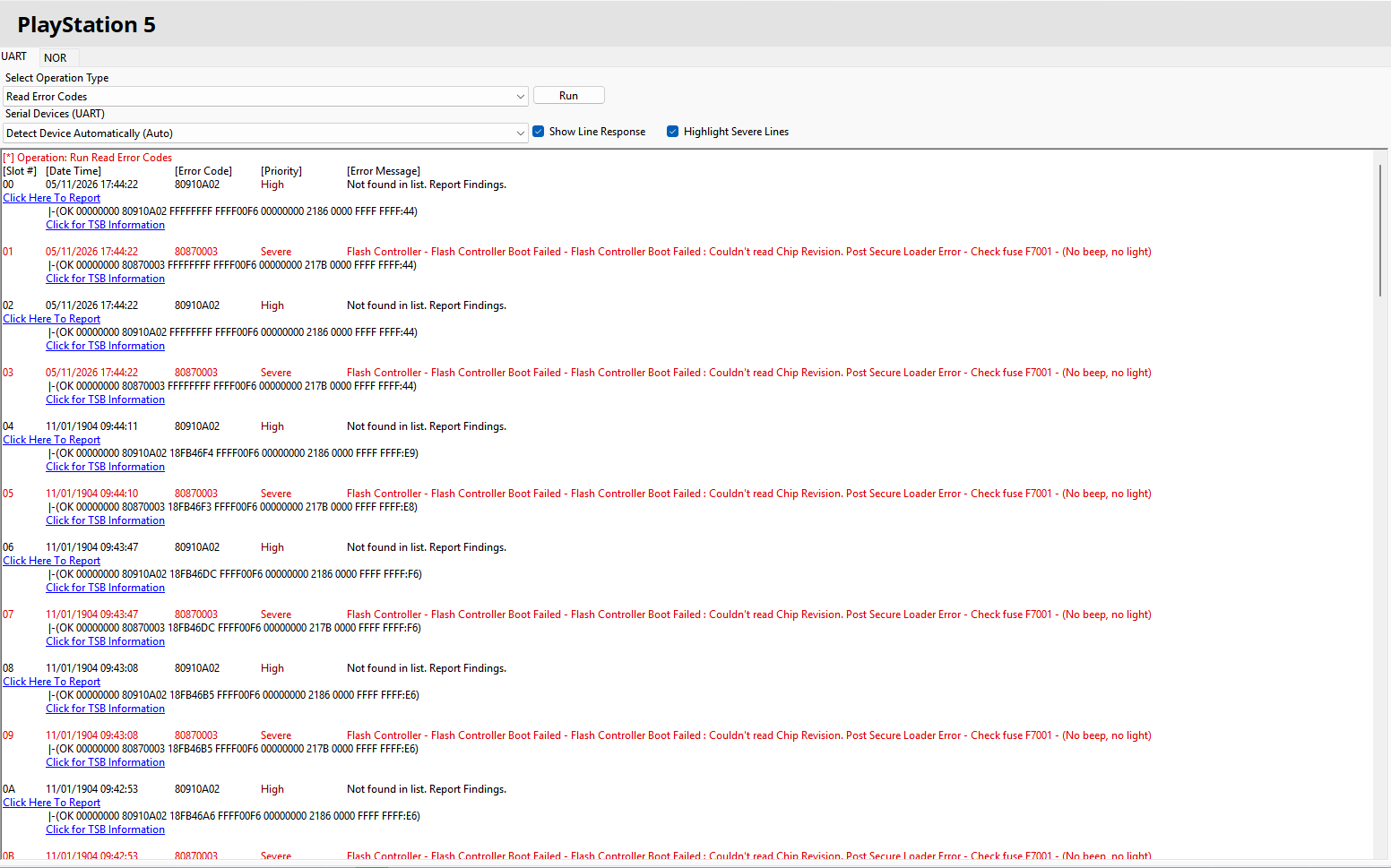
However, it does not respond when I try to read the error log. Console Service Tool 1.0.5.0 returns:
[*] Operation: Run Read Error Codes
[!] Operation Cancelled
A separate web-based UART tool receives the same messages but reports “No answer from console” when requesting the error log.
Measurements and checks performed:
Original PSU connected: 12.24 V at the motherboard input.
With a bench PSU at 12 V, the board settles at approximately 8 mA. I have not confirmed the initial current transient.
F7002 and F7502 pass continuity tests.
Measured 5.11 V on one pin of the IC marked FK2QA and 3.31 V on one pin of Y182D. These are individual pin measurements, not a complete verification of the standby rails.
No abnormal heating observed with a thermal camera in standby.
With the UART adapter disconnected and the motherboard powered in standby:
PS5 TX to GND: 3.31 V
PS5 RX to GND: 3.31 V
UART setup:
I use a CP2102 USB–TTL adapter:
PS5 TX → adapter RXI
PS5 RX → adapter TXO
GND → GND
Adapter power pins left disconnected
The adapter initially had incorrect voltage levels. After a PCB trace modification following a guide, its 3V3 output measures approximately 3.3 V and TXO measures 3.34 V at idle.
It passes a loopback test: transmitted text is received exactly, and removing the TX–RX jumper stops the received echo. The repeated PS5 messages are readable, but command responses are absent.
The UART tests on the console were performed using the original PSU.
Questions:
Has anyone encountered this repeated message on an EDM-033 with no beep or power-on response?
Can this indicate a fault in the motherboard’s AC_IN_DET sensing circuit, even with 12.24 V present?
Which test points or components should I check to verify AC_IN_DET and the associated standby supply?
Could the console be stuck before accepting UART commands, or should I investigate its RX signal path first?
I can provide motherboard photos and screenshots of the UART output.
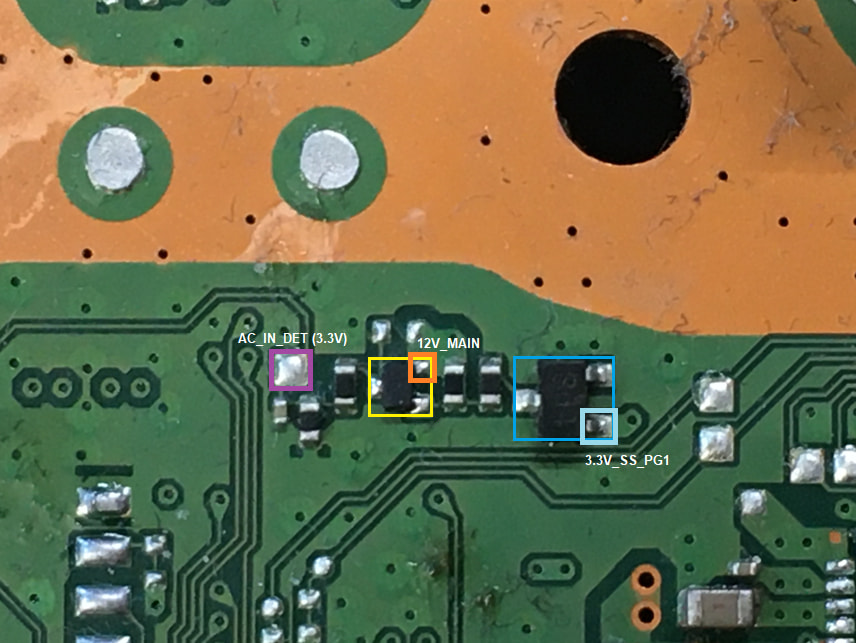
I would check the AC IN DET ciruit:
The blue transistor 3.3V at the light blue input and the yellow transistor should have 12V at the orange input. The violett point should read 3.3V.
Hi, thanks for the reply—your help is truly invaluable. I’ve taken the measurements you requested.
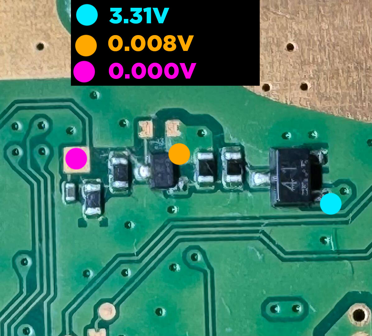
On the BLUE transistor, I’m getting the correct 3.3V reading at the LIGHT BLUE point, but I’m not detecting any voltage at the ORANGE and VIOLET points.Could you tell me what the problem might be? Or perhaps give me a clue to help figure it out?
Thanks!
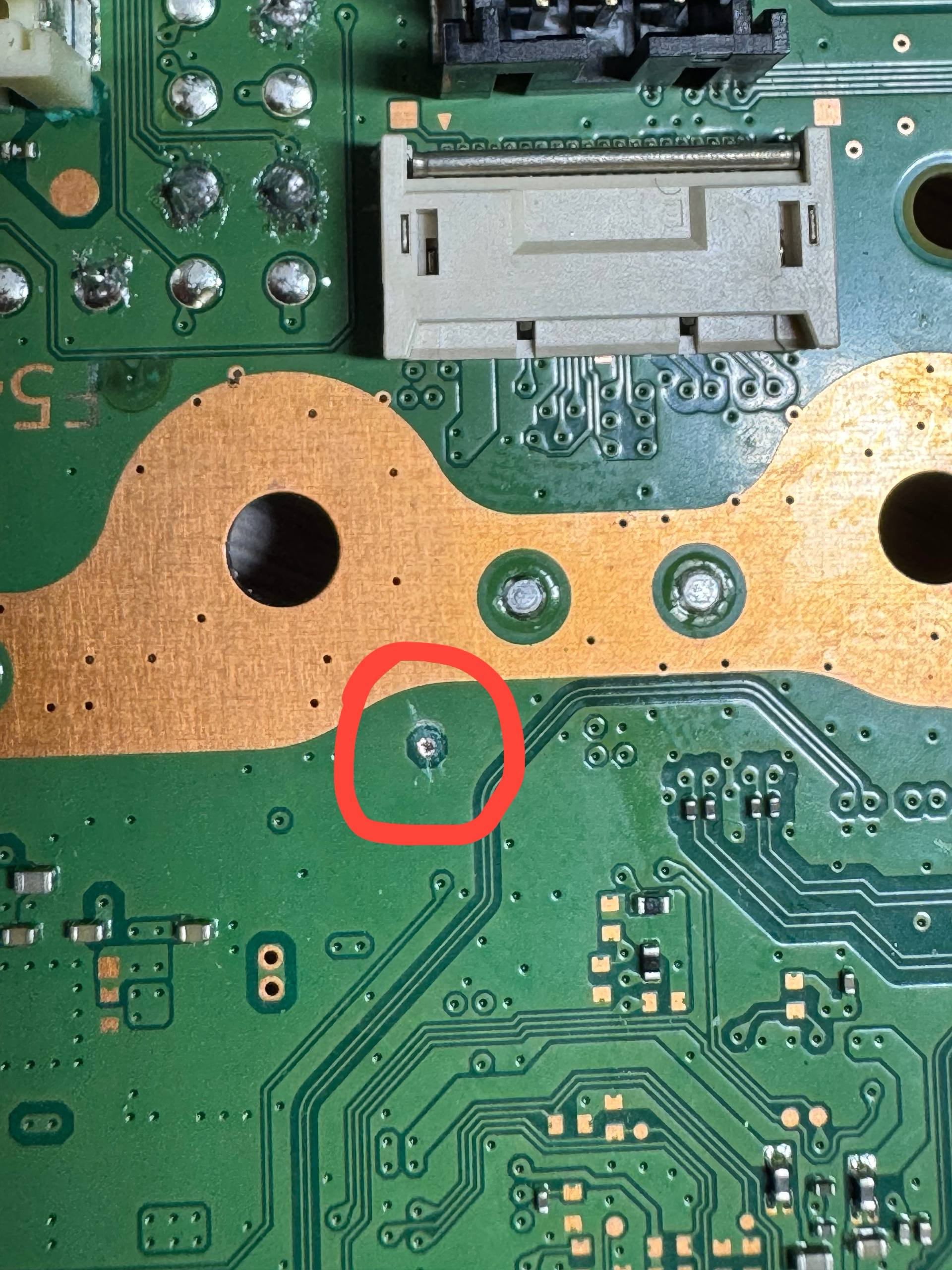
I also took a new, higher-quality photo; it might be useful for other users experiencing a similar issue, but I’m unable to add it—it says that adding media files is not possible
Unfortunately not; we don’t have 12V at that transistor (there’s about 0.005V–0.008V), and 0.000V at the purple point.
However, 12V does reach the board—I’ve verified this by measuring the main input.
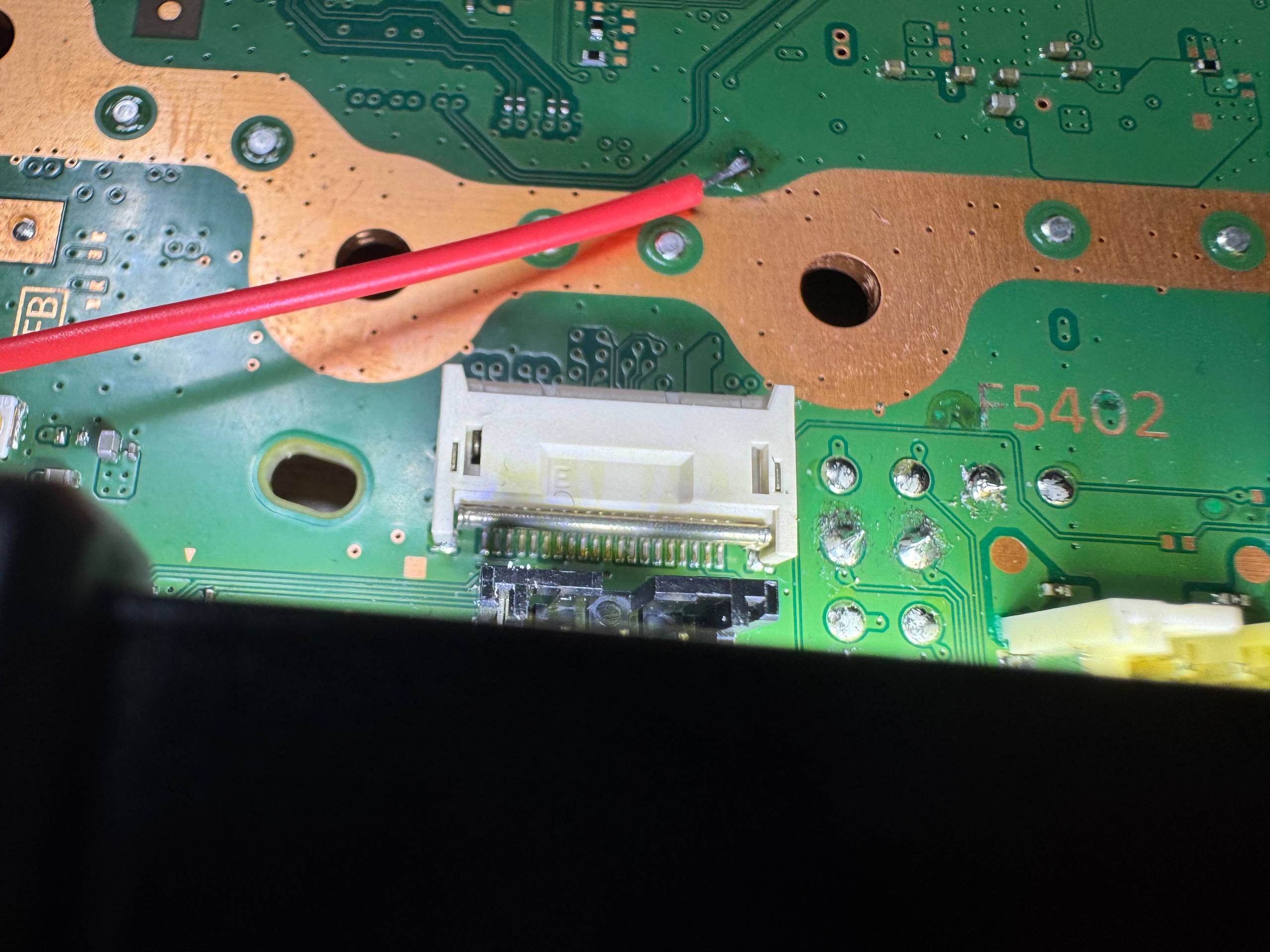
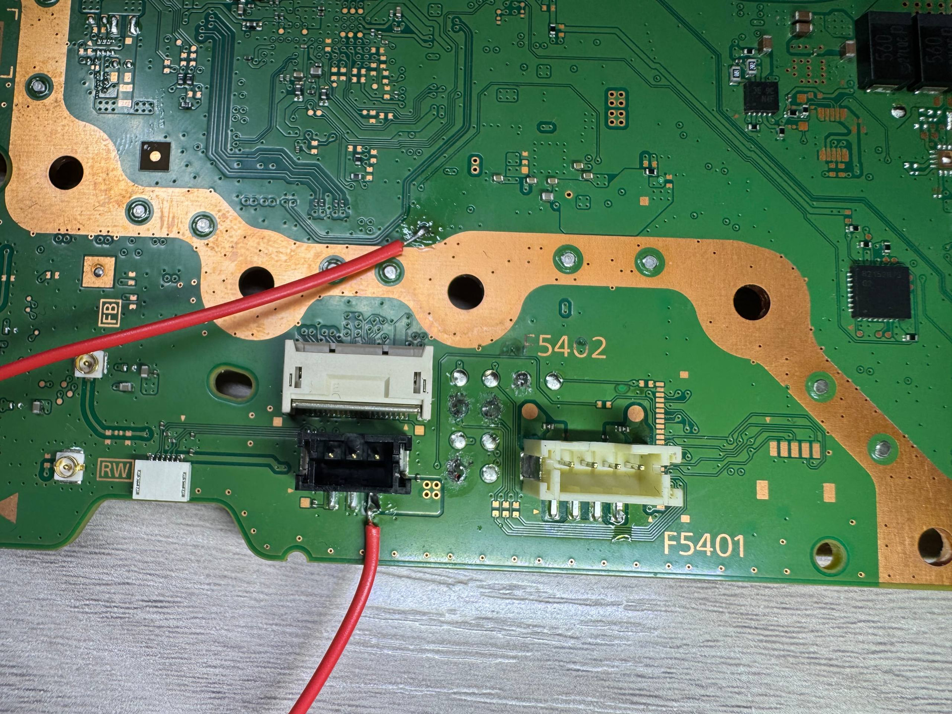
That is odd. Usually there is nothing between this 12V patch and the 12V line. On the backside is on the exact same spot a via. I would scrape the mask away and check if 12V are there present. And please check the 12V and the fan connector.
I’ve noticed some rather strange behavior. On the 12V input connectors (the ones that plug into the power supply unit), when set to diode test mode, the positive and negative pins show a short circuit with a very high resistance; however, this does not happen every time (the test was performed with the power disconnected).
Yes, I was also thinking about creating a bridge between the fan pin and the exposed area, but I wasn’t sure if that would be a good idea.
There are some spots on the board with pads where components should be, but they look too perfect as if they hadn’t actually been removed by anyone…
I’ll go ahead and try creating this 12V bridge. let’s see what happens!
I can take a photo for you right now, no problem.
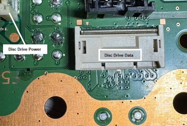
By “disc drive connector,” do you mean the connector for the expansion SSD or the one for the SSD control chip?
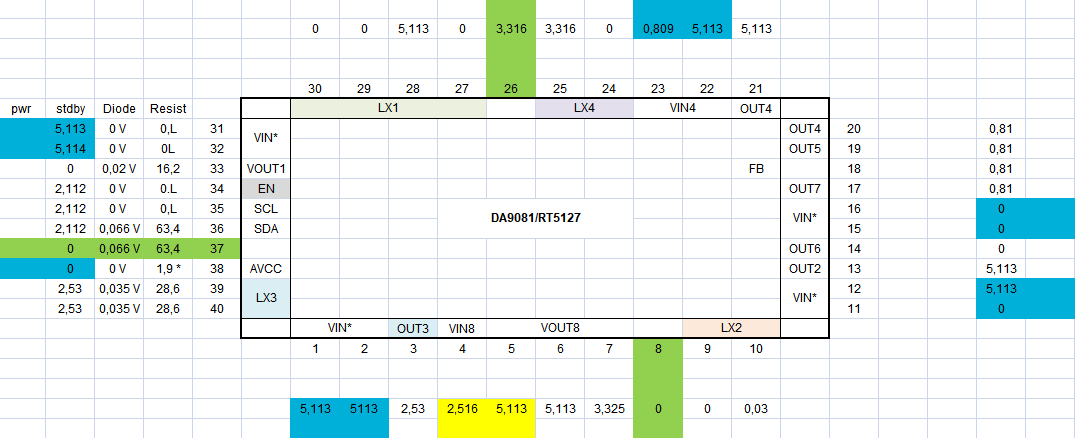
I’ve taken some measurements; I’ve attached a screenshot.
They are completely different from yours—does it make sense to continue taking measurements on the other pins?
Also, I ran a test: the PS5 now emits a beep when turned on (though the LED and fan show no signs of life), and the processor gets slightly warm.
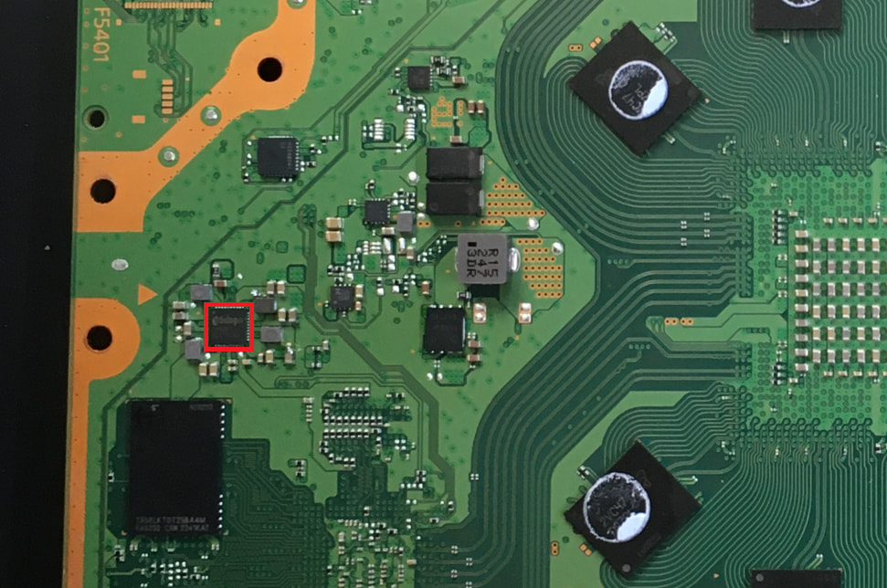
Sorry, I should have send a picture in the same orientation like the table. In the table pin 1 is down left and on the mainboard where the riangle and the dot on the chip are top left.