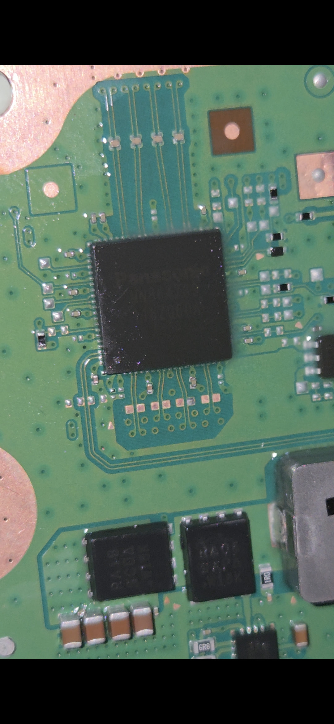
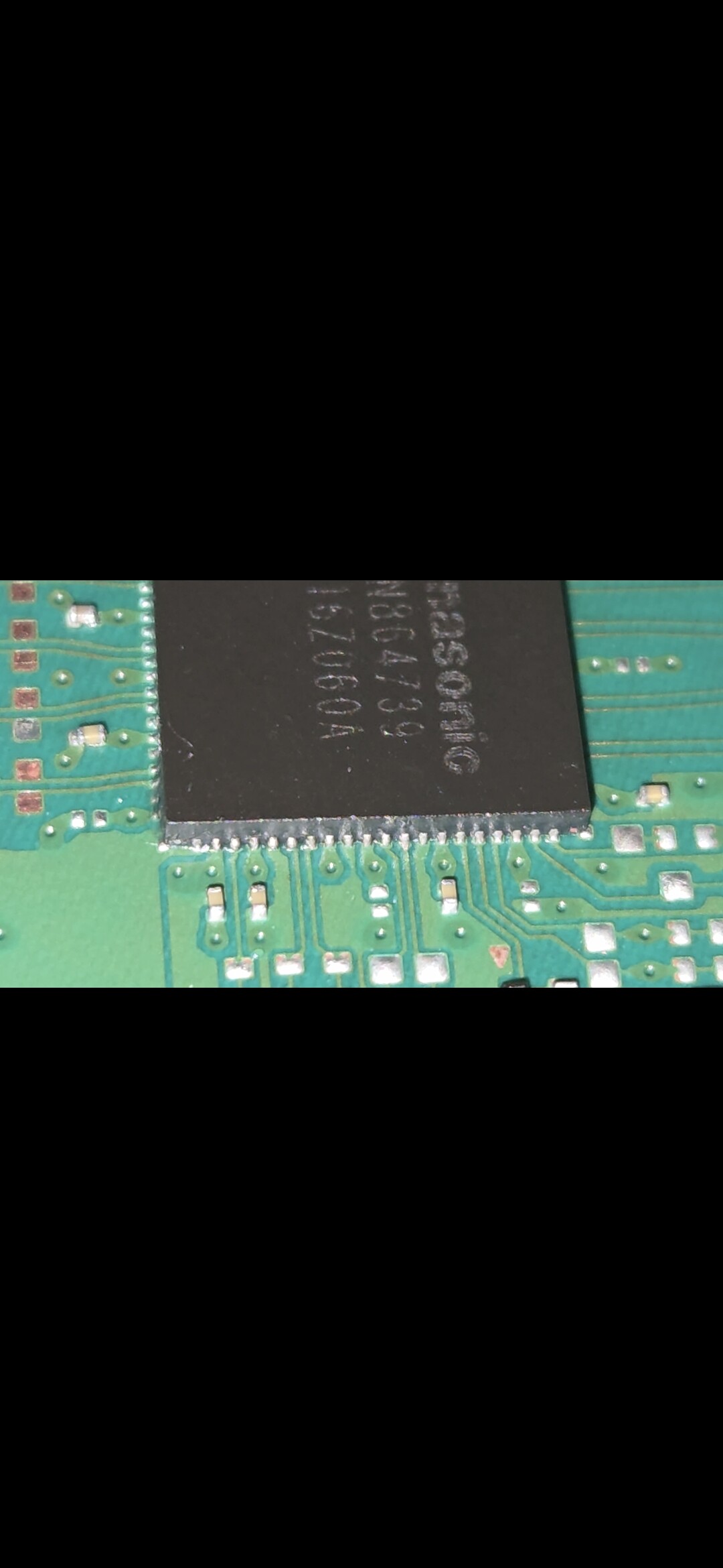
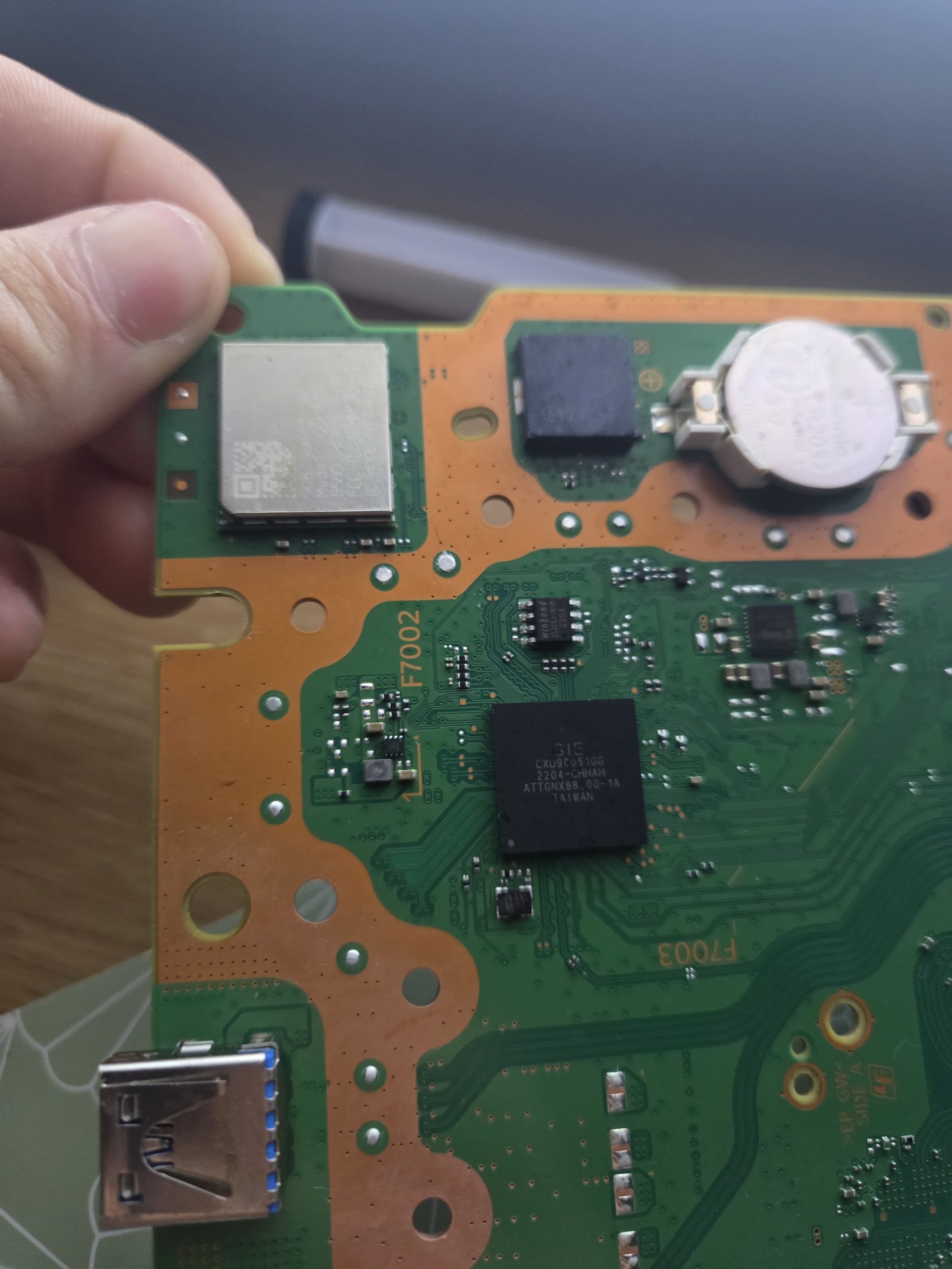
Context I installed a new Panasonic video encoder and knocked off some caps after lighting damage.
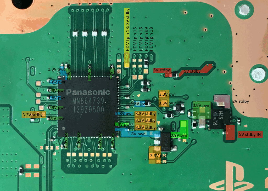
My question is what should I look for while waiting for the caps to come in to make sure the encoder works? I am curious if the encoder was 100% install properly (How do I add images?). And if you think I should check anything else that would cause no video.
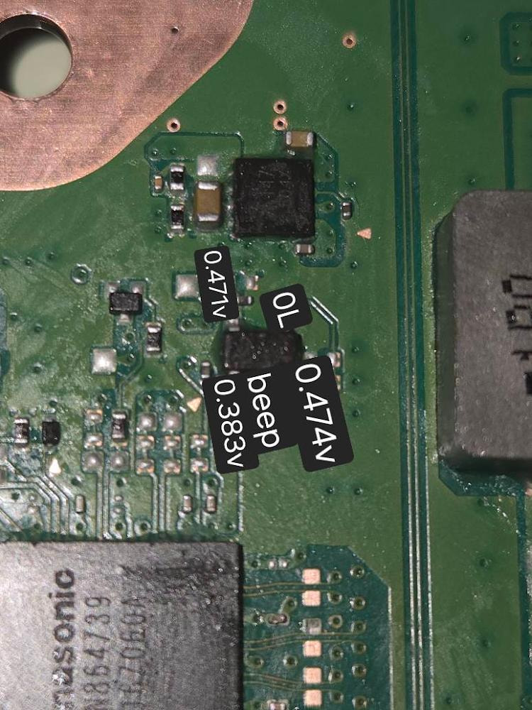
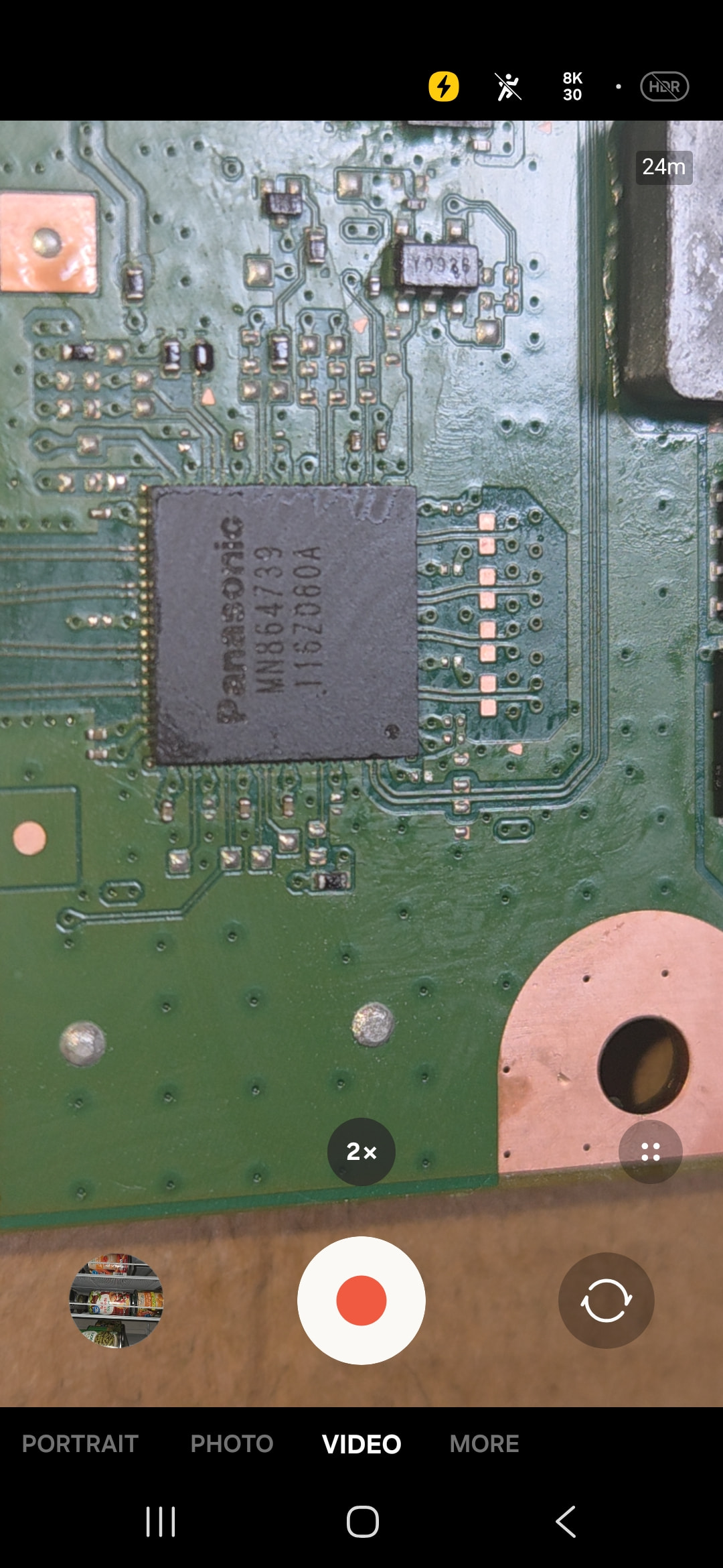
Okay nice I was able to add images the aerial view you can see i am missing at least 3 caps and i accidentally put soldering on thag copper but i think its fine?
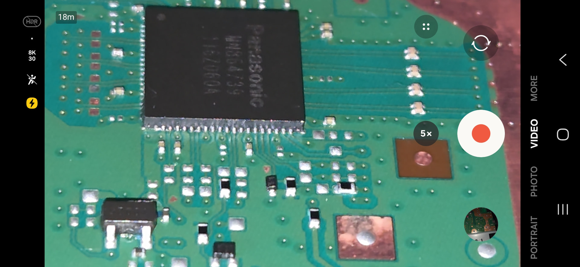
This image is after my first solder job which shows the caps (not currently what it looks like). Please dont judge to hard.
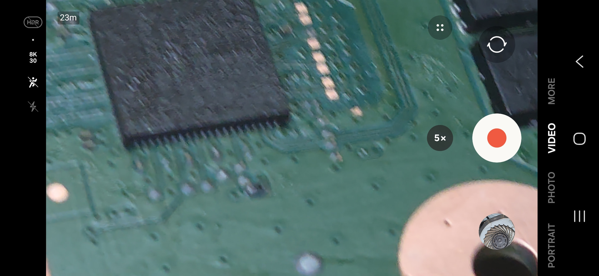
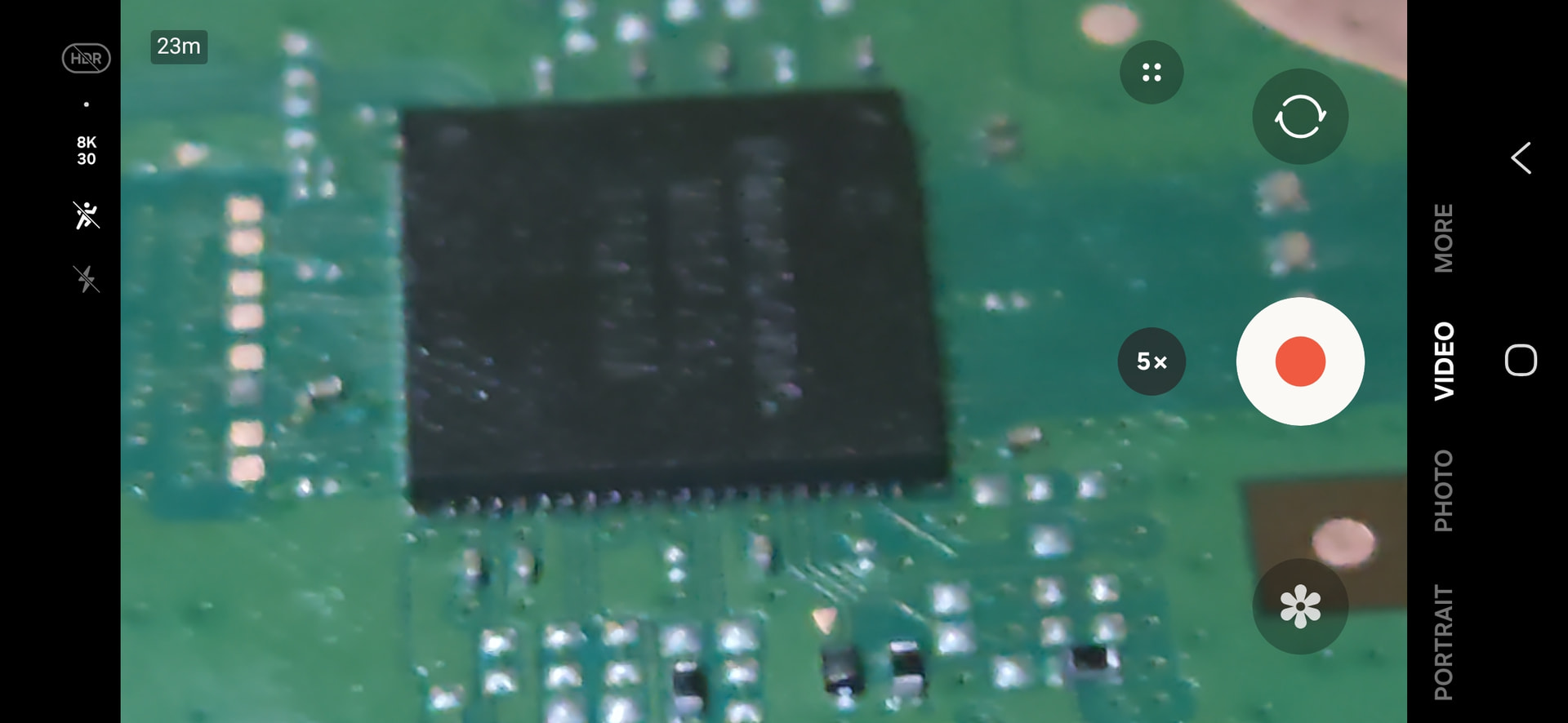
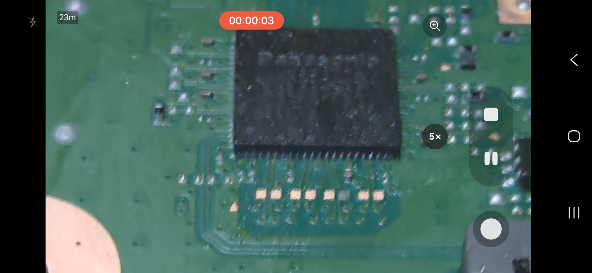
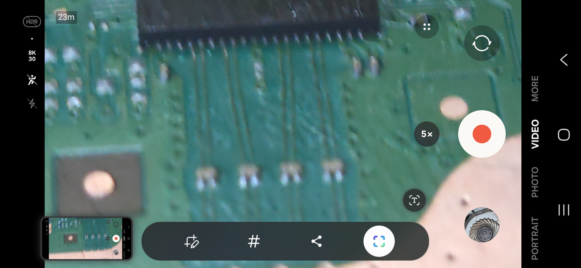
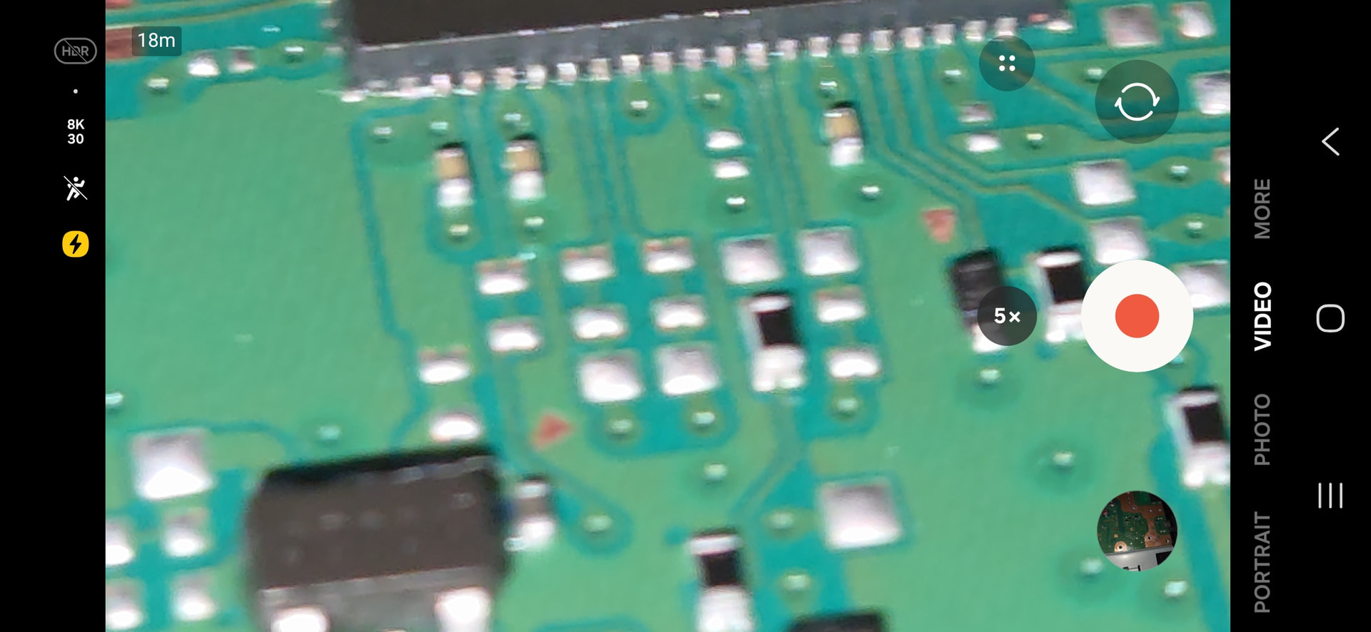
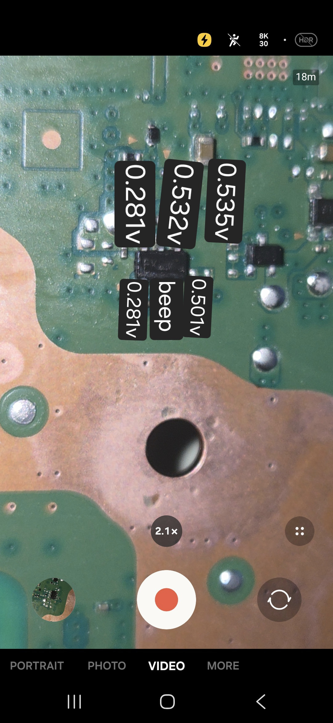
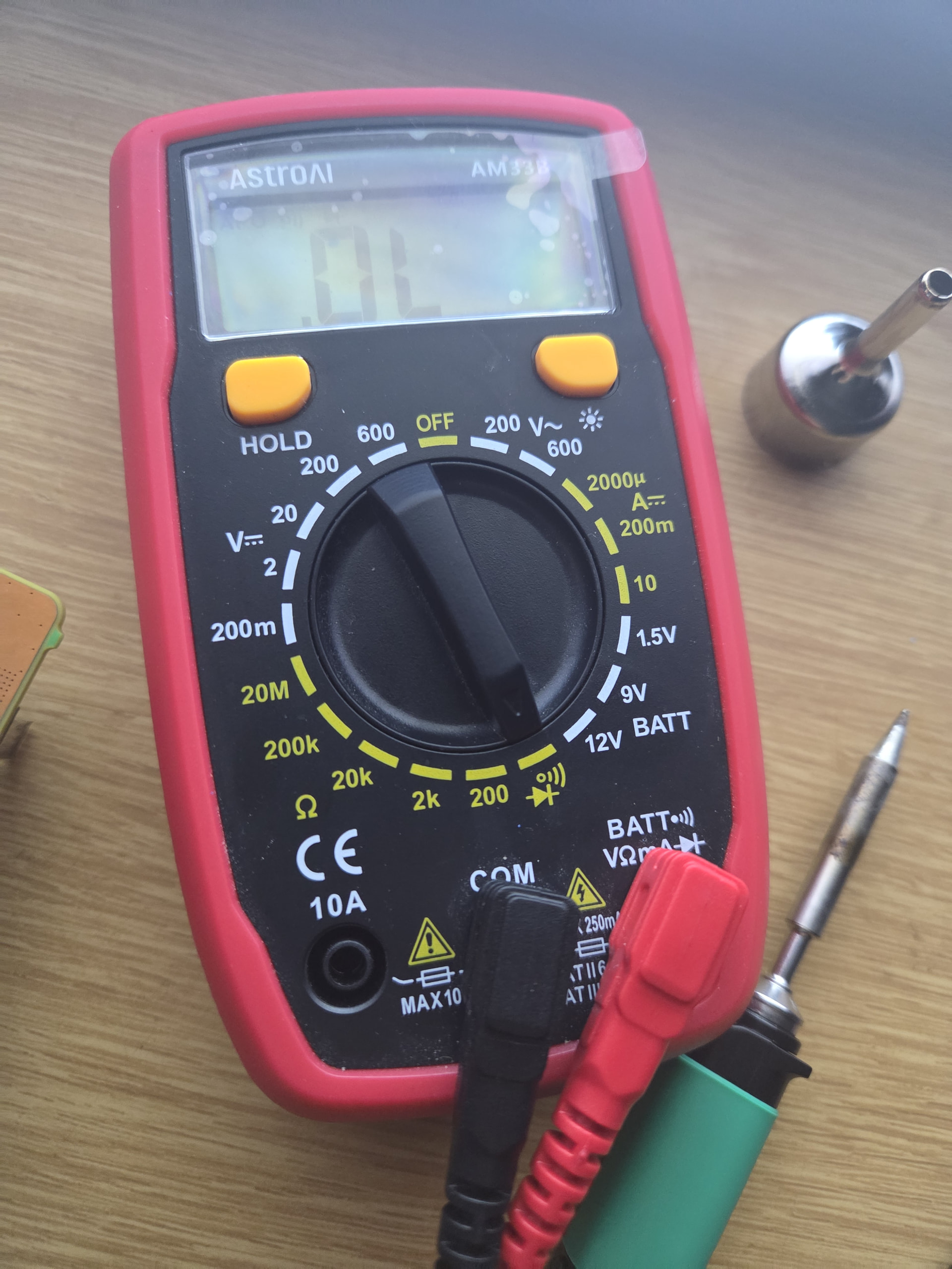
Rough for me my AstroAi AM33B probes are too thick and they measure two at a time instead of one . Also an image of my solder job a bit blurry because I am using my phone for all of this. I am going to try to bridge my probe with my tweezers to get some reading. Also just to make sure I order the right caps the ones I need 0402 ceramic caps?
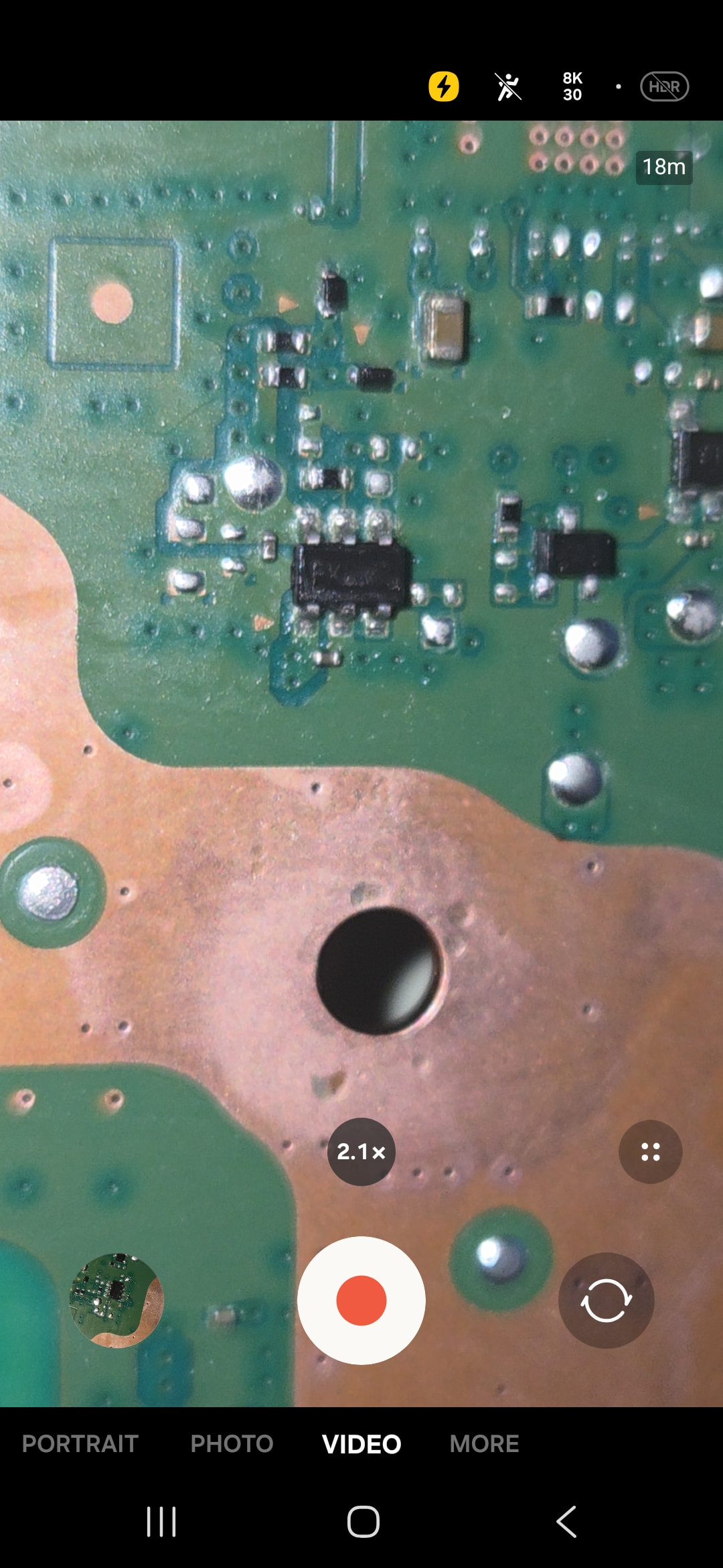
remove that 6leg switch controller IC and check the 1st pin(bottom left from your picture) reading comes back 0.5v or not. The 1st pin is 5v stand by should not have 0.281 low reading
Just so I understand you want me to touch the letters and or numbers on f7002 and then touch pin 1 of the spot where the chip was removed? sorry this is my first time doing this stuff and I think it matters which probe I use for my measurements since it has continuity and diode mode on same thing.

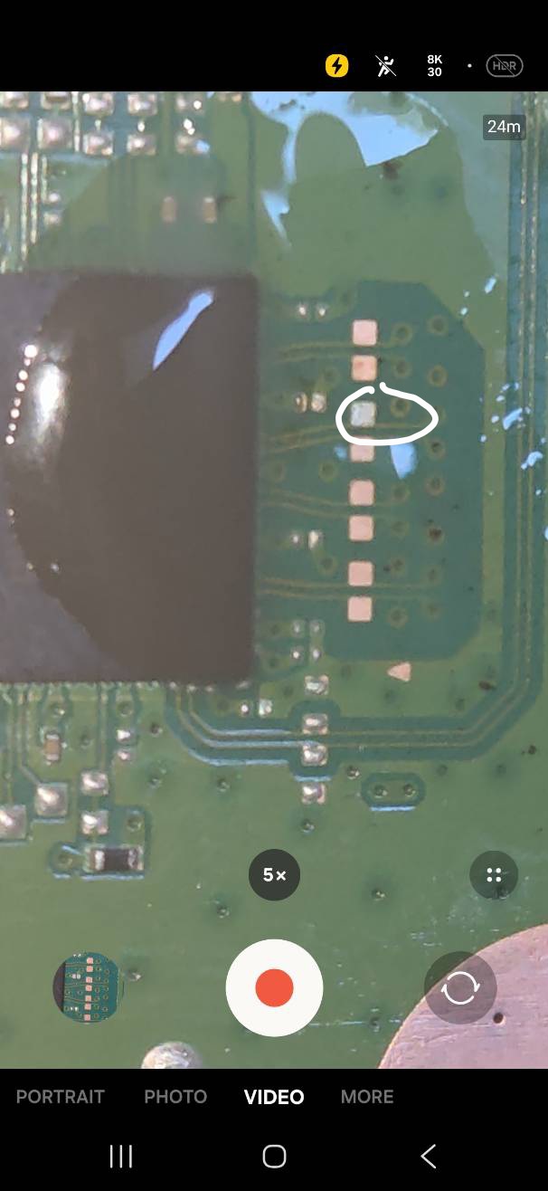
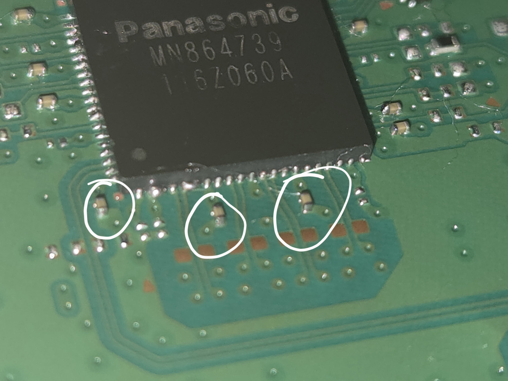

 . Also an image of my solder job a bit blurry because I am using my phone for all of this. I am going to try to bridge my probe with my tweezers to get some reading. Also just to make sure I order the right caps the ones I need 0402 ceramic caps?