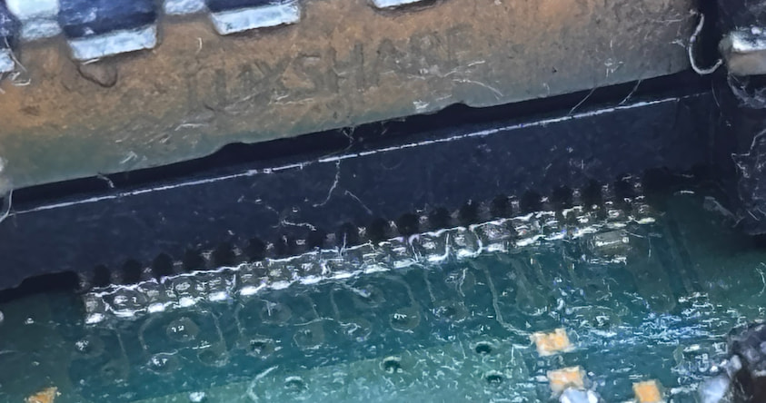
Hello. I was dealing for some time with loosing signal while in game on my fat ps5. It would boot and show video no problem, but when I would game it would suddenly start showing noise and loose signal. Sometimes when I unplugged the cable and plugged again the video would come back and I could play for another 10 minutes.
I was playing around with software changes, resetting vide, refresh rate, resolution, HDR all different things, clearing cache in recovery mode.
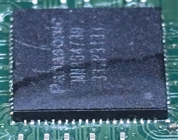
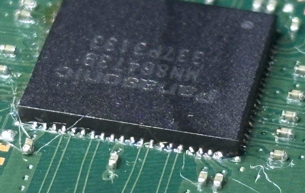
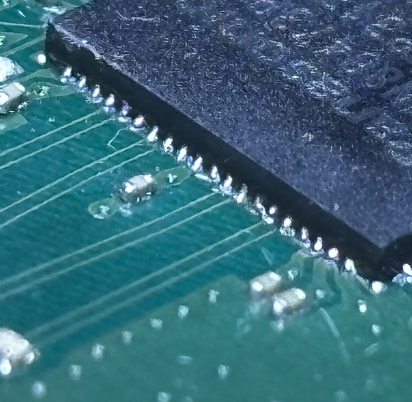
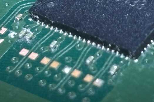
Then I’ve started looking into hardware, some googling and AI pointed to HDMI IC potentially broken. I’ve ordered one and replaced. After that video signal gone. PS5 booting into white light.
Since then I’ve even ordered another IC to check if it was faulty. No luck.
I am confident about good soldering of the chip.
Since then I’ve done many different measurements for shorts, bad caps, res, diode mode reading in many places related to HDMI circut. I’ve also done voltage measurements on power on, check the continuity of the HDMI port itself using breakout cable. All seems to be OK but no signal. I am running out of ideas what to diagnose more.
Below a summary from AI of things measured:
PS5 CFI-1100 / EDM-020 — no HDMI signal
History
Original symptom: intermittent signal loss, always present on boot. HDMI encoder (MN864739 / IC3001) replaced on suspicion. From that point: no signal at all. Console boots blue → white and stays on.
Encoders tried: original (removed, refitted), one unmarked replacement, one new. All three: identical result.
Measured good — power
- FB3001, FB3002, FB3003: 1.79–1.798 V
- FB3004, FB3005: 0.89–0.895 V
- Core rail 0.9 V present → chip asserts its own PWRON → encoder is alive
- IC7008 (5 V switch): two pins at 5 V, passing
- F7001, F7002: 0.2 Ω
- Rail Ω at IC: 606 Ω with chip fitted, 3790 Ω with chip removed
Measured good — passive
- L3001–L3004: ~2 Ω, all matching
- FB3001–FB3005: 0.3 Ω
- R3018 4.7k, R3020 6.8k, R3022 27k, R3023 1.8k, R3024 1.8k, R3028 22R — all in spec
- No shorts on IC footprint; all pads OL or 0.000 after removal
Measured good — port (diode, via cut HDMI cable)
- TMDS pins 1,3,4,6,7,9,10,12: all 0.81
- DDC 15,16: 0.67 · pin 18: 0.54 · pin 19: 0.69 · pin 14: open · grounds 0
Live at port (cut cable, no TV attached)
- 18, 15, 16: 5 V
- 19 (HPD): 0 V — expected, nothing on the far end. Untested with a real TV.
Notes
- One suspected open resistor (R3022) was replaced; later measurement of the removed part read correct, so it was likely a meter-mode error, not a fault.
- Sony service manual sm-ps5-0043e-01-0 in hand, schematic and parts list.
Outstanding
- HPD at pin 19 with a real TV connected — the only untested item.
- If HPD is fine: I2C encoder ↔ southbridge, or DisplayPort link from the APU. Neither measurable with a multimeter; needs UART log or a scope.