3.3V is not shorted. I have had cases when this 3.3 was missing it was one of the caps under the wifi ic but this is one is strange. Pin 13 enable does not have any voltage (0V). Resistance to ground on this pin is in 100K ohms.
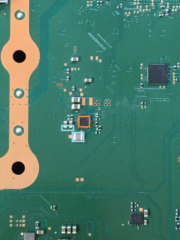
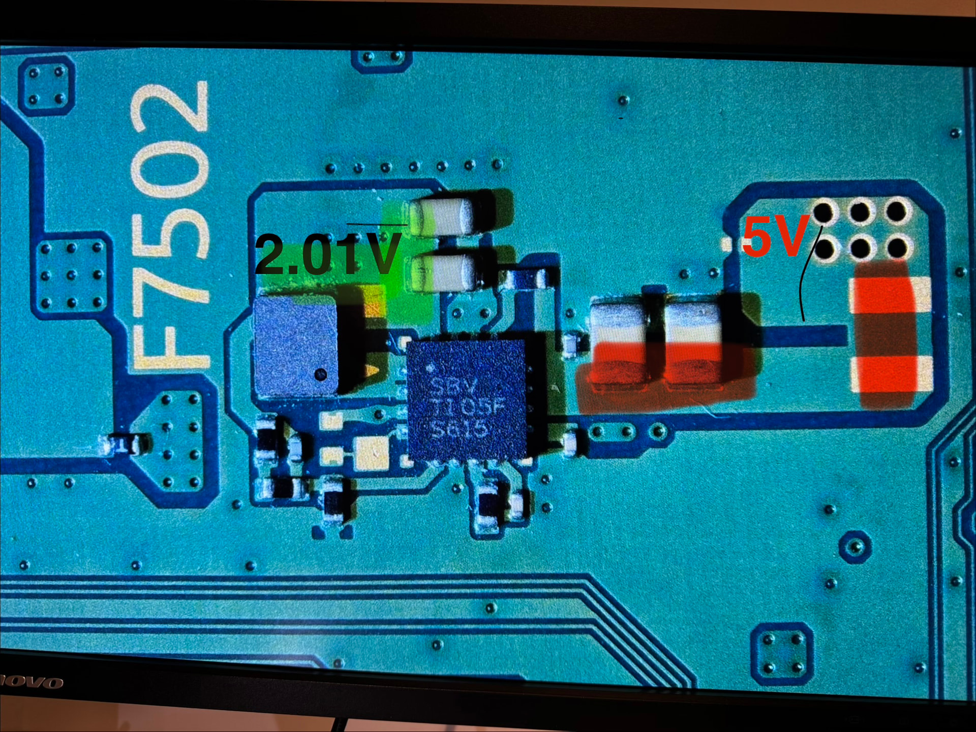
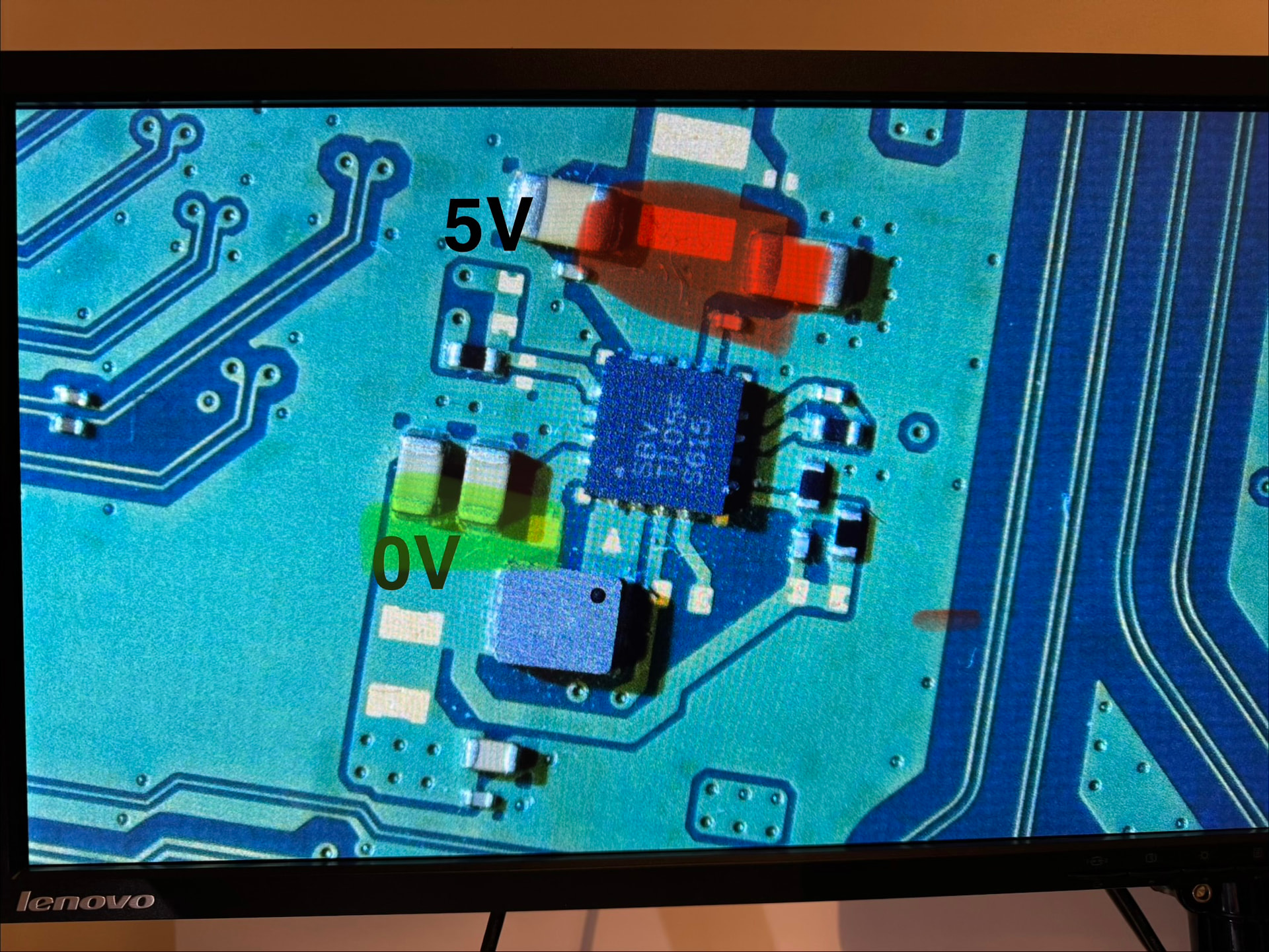
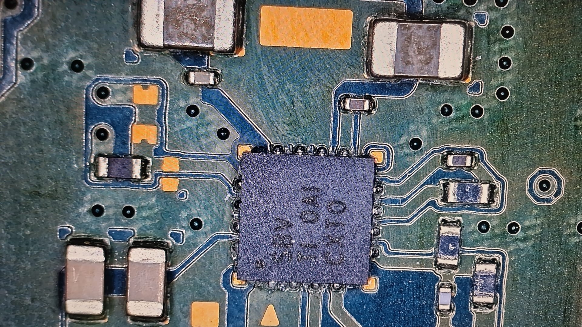
There are 2 such chips at the back. The one near F7502 has 2V output and the one near USB circuit has 0V output. The exact one you shared, i couldn’t find it on my board.
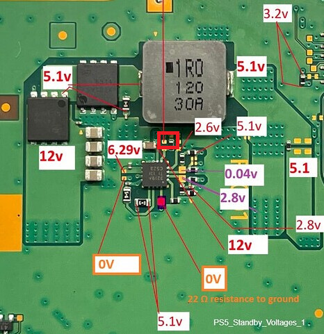
Yes 5.1V input is present at the chip (at pin 3, 10,11,12). Resistance to ground at light blue marked caps and coil is more than 100K Ohms and climbing.
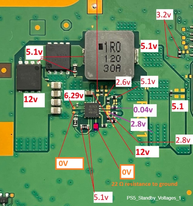
What keeps bothering me is the 3219A chip having 0V standby at pin 16. I also replaced this chip with the known working one but still same behaviour. The resitance to ground is 22 ohms. On a working edm-010 board i always get 5V standby.
Even with the chip off the board this test point has 22 ohms resistance to ground.
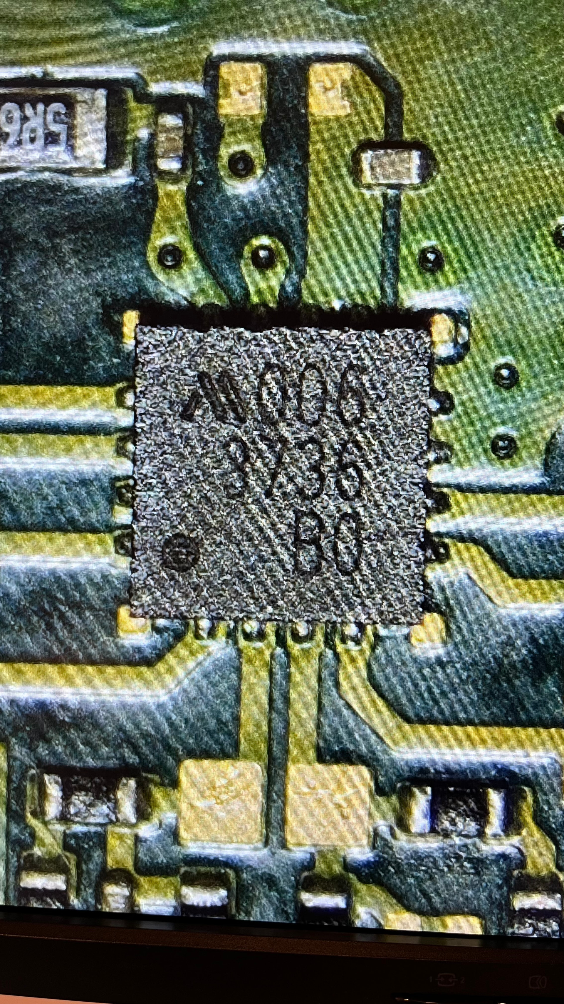
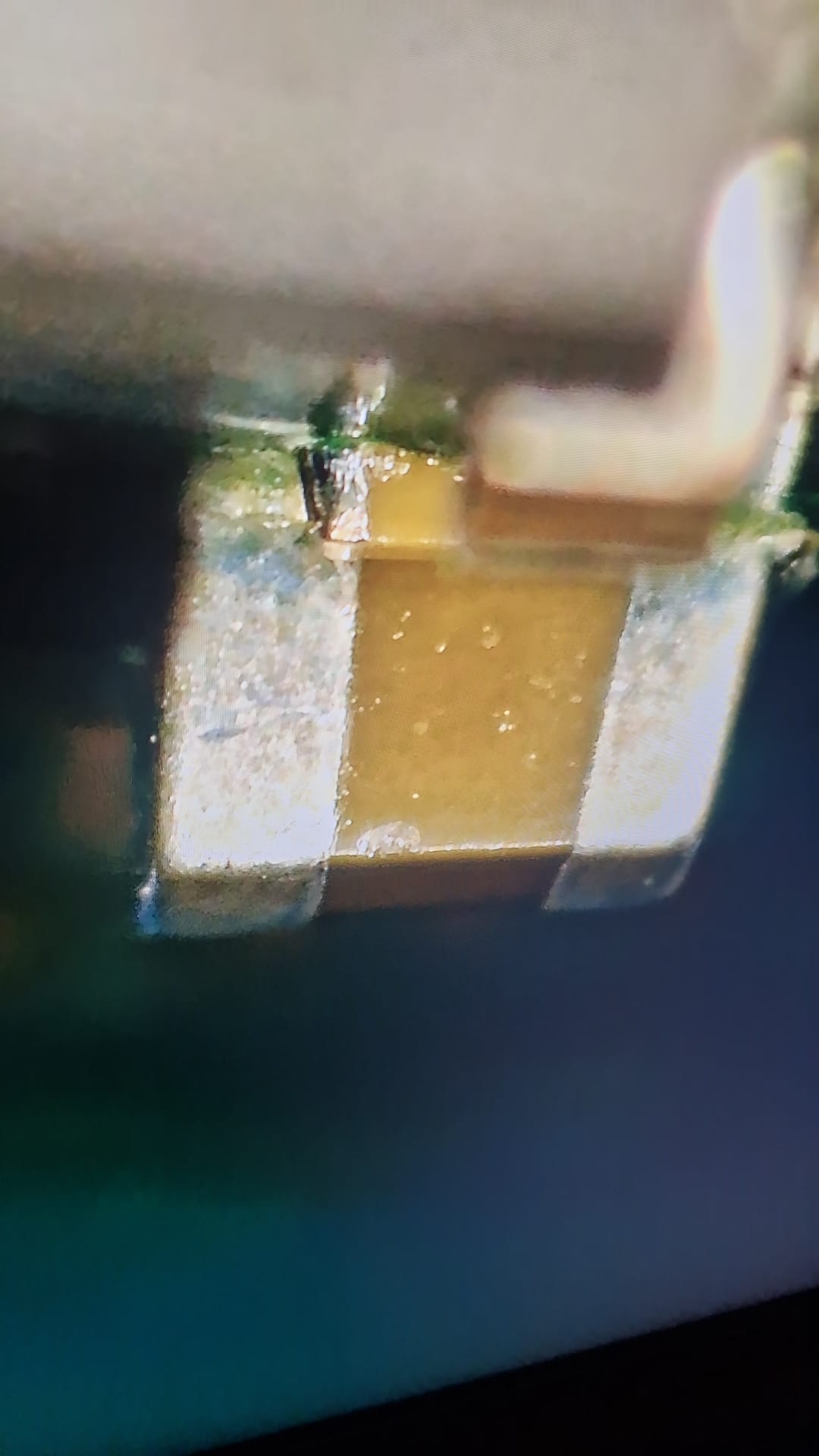
Btw on the original board, voltage regulator that generates 5V was from a different manufacturer. Here is the photo of the original part which turned out to be bad.
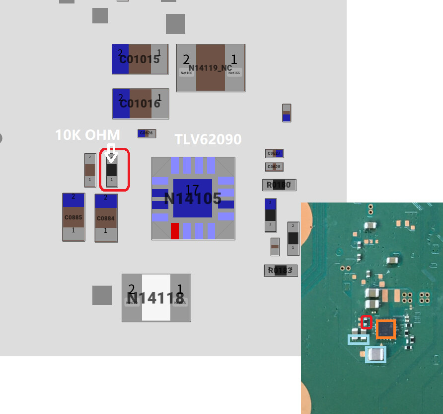
Sorry, I was not clear. 100k ohms was the resistance of the resistor (highlighted by jkyoho) in the circuit which should measure 10k ohms. It led me to doubt TLV62090 chip having internal damage. You were correct pulling TLV62090 chip resulted in a good 10k ohms resistance at pin 16 (PGOOD) of 3219A.
I just installed a known good tlv62090 and now I have 5V at pin 16 of 3219A and all standby voltages are back. Thanks a lot for pointing me to the right direction.
I’m joining in because I have a similar problem.
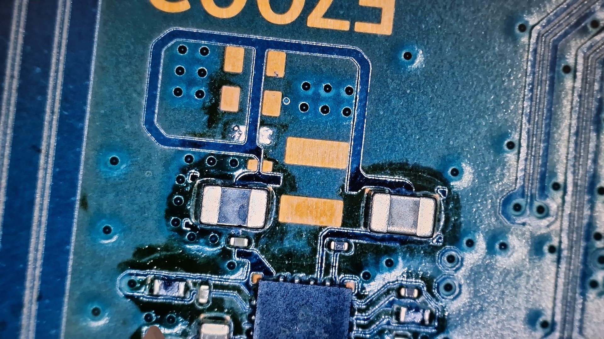
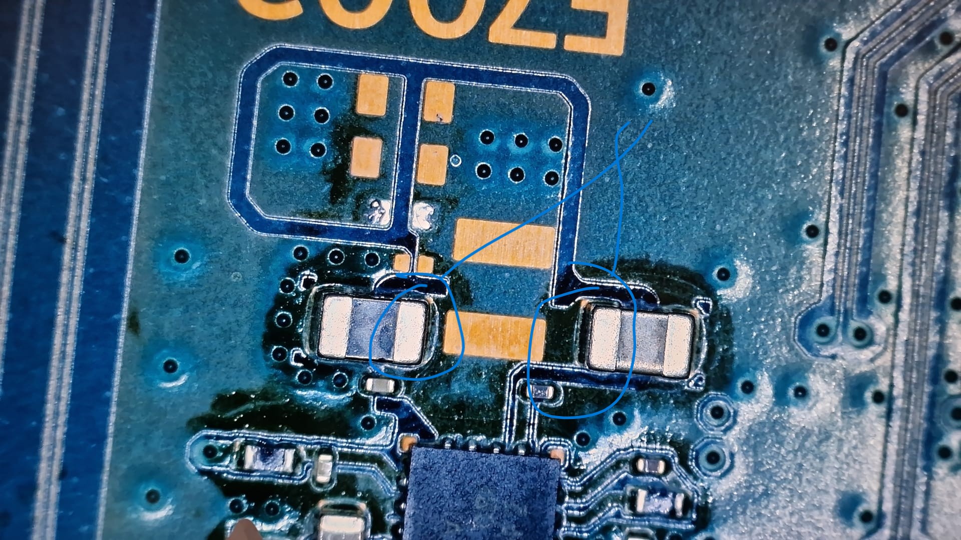
UART directed me to area F7002 - 5V Short
The fuse was open. I removed it, but before replacing it, I detected a short on the capacitors in the photo (upper part)
On one side of F7002 and on the other side.
I tried injecting 1.5V - 1A fuse side, but I didn’t find any spots with the thermal camera.
I’m injecting 1V-1.5V - 1A-2A, I don’t see a hotspot.
Where does this 5V come from?
The output is 3.3, which goes to the Wi-Fi if I remember correctly, and it’s fine.
The problem is only on one side of the F7002, the left one.