ok. I might try pulling these ICs you mentioned in the future… BUT I think I will let this one RIP for now and mark it as donor board. shame though since it’s an unpatched unit. @Severence thanks so much for all your adivce and your time!!
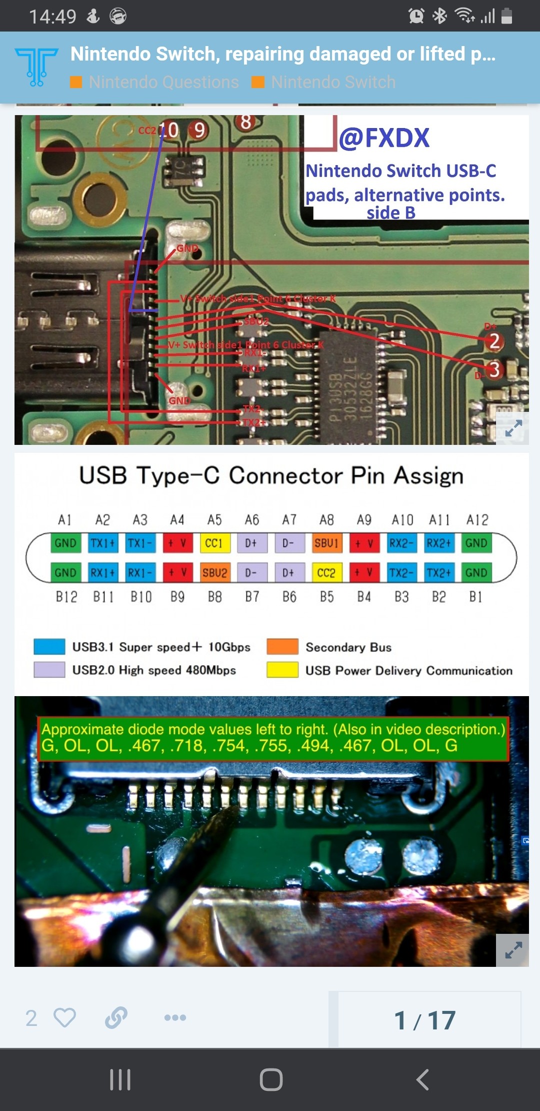
Hi, sorry to jump in. Interesting problem. Might be worth measuring visible connector pins in diode mode. If you Google nintendo switch pinout you should get picture on what is supposed to read. Red probe on ground in diode mode.
Not sure what is your multimeter shows but pins from either sides are ground, second and third pins from either side are open line (not zero) and not the same as ground. This is tested in diode mode (not ohms/resistance) with red probe on the ground. It might be just the way your multimeter shows open loop/line. Sorry just felt the need to clarify.
Now to your short, try in same diode mode on both sides of that capacitor. You could try using ipa(or lighter fluid) to wet board with bench power supply connected and amp limited to see where it will evaporates first. Before you do that if you have working board you can try to find where tracks connected to which components that can help to see where possible problem may be. How I wished schematic for nintendo to fall off the truck would made it so much easier to troubleshoot.
When there’s a short to ground, usually voltage pulled down by the short and as you are measuring 1.8v or close enough, short is not convincing . Also all lines on pins are good. I got 3 switches left all with different faults (some awaiting parts) but I guess being technician and have all tools helps in detection.
true that. I am thinking about getting a thermal camera, also a better meter. Could still take a while though. If there is anything new I find, I’ll post it here.
a thermal camera would be a waste of money in this instance as the current draw is too low
The only people that would suggest otherwise are the people selling them… if there was adequate current draw, you’d find it with your finger long before a thermal cam even booted up.
In your case, there’s no way round it unfortunately, you’ll have to pull components in order to clear the short and ultimately find the culprit
You could try using thicker leads from your PSU incase the wires your using currently are dropping excess voltage, just hook some fine fly leads up to the relevant points on your board, and then connect your thicker wiring up to that. Keep all wires as short as possible.
OK noted, it seems to be a fun tool though, I always wanted to see the world with the Predator’s different viewing modes
could you explain about the thicker leads for my PSU? I use the standard cables that came with the PSU with banana plugs on one end and crocodile clamps on the other. What would be the effect here if I use thicker cables? would it lower the resistance? and therefore increase the current?
for the fly leads would it be enough if I split some braided copper wire and take one of the fibers, or would you recommend getting some jumper wire, for example 0.1 or 0.2 mm thickness?
and which other points would you recommend except the + of the cap?
is there actually a way to check if that cap is working fine? like, I took it off the board and tested if it’s shorted, but that does not seem to be the case. Can I measure the capacity somehow and see if it is as its supposed to be?
Haha, just get one of those fake thermal camera apps on your phone and pretend
You got it
Provided it’s insulated, using bare copper here is asking for trouble, depending on what I’m soldering my fly lead up to, I’ll use enamled wire or plain PVC insulated hookup wire (i think it’s 7 x 0.1mm) and then connect my chunky PSU leads up to that.
Yeah, you can take it off the board and check the resistance accross is and see if it’s short, should read in the high megs or OL. You can also check it’s capacitance. Though tbh it’s unlikely the cap is at fault.
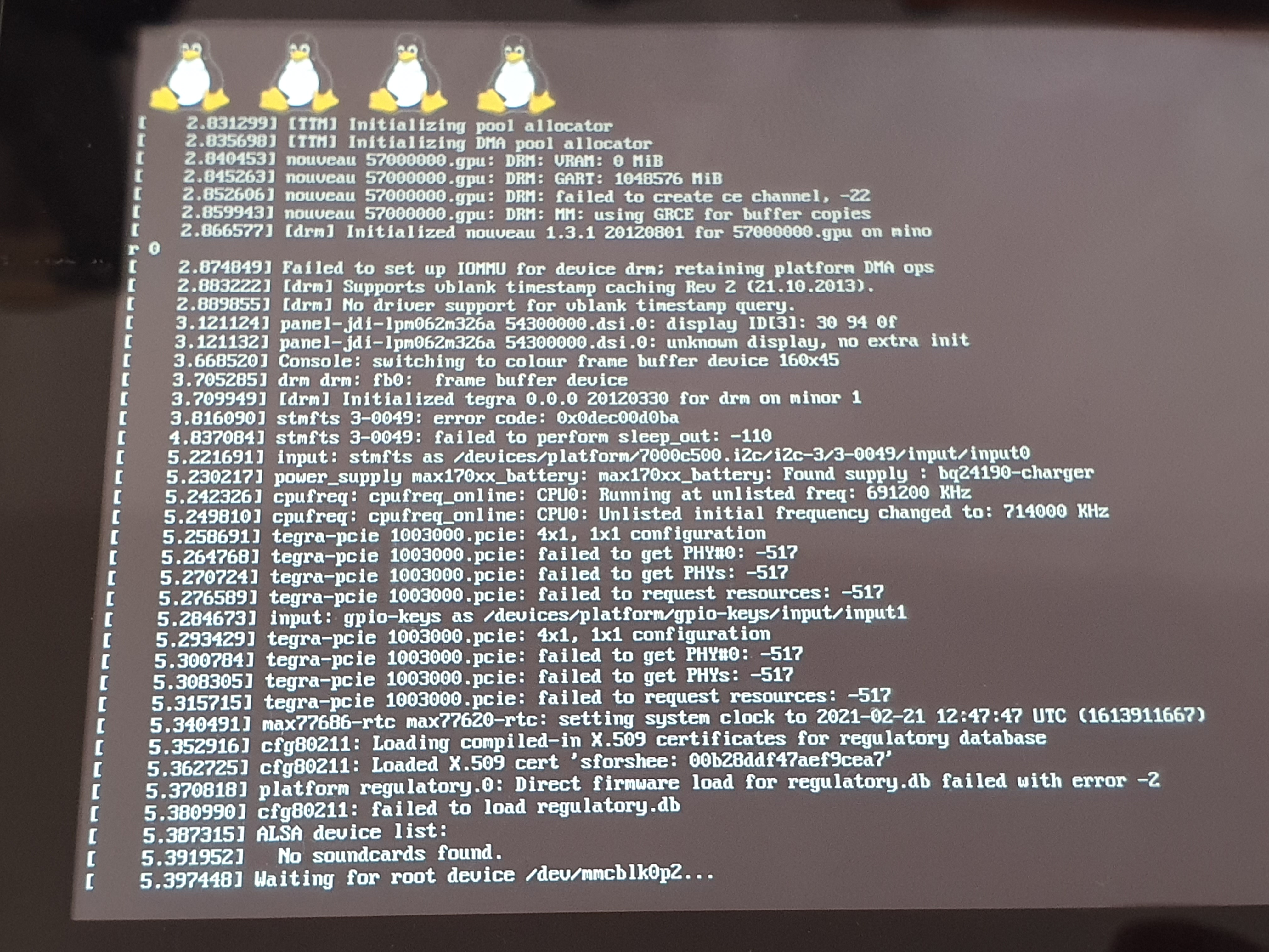
lets first get back to what we wrote earlier in PM, thought its also good to share that info in case other people find it interesting or helpful. I compared the linux boot logs of my faulty Switch and a good Switch and indeed there are some differences, especially the line “Failed to set up IOMMU for device 57000000.gpu…” that pops up multiple times.
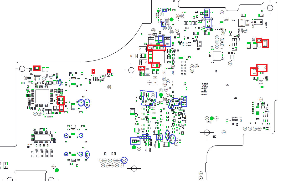
Additionally, before pulling anything off, I took out the board one more time to check some components using @Calvin 's diagrams (HUGE thanks for those, they are very helpful!!! ) and I found loads of shorts to ground on the back side of the CPU (or GPU? that nVidia thingy… I think the one you call SoC ), RAM and other places. Look at this image, I marked them all BLUE (ignore the red squares):
I tried to measure as many as possible, but I might have missed a few, so there might even be more places.
my multimeter beeps but shows a resistance of 7 Ohm at all those places with the short (the ground side shows 0).
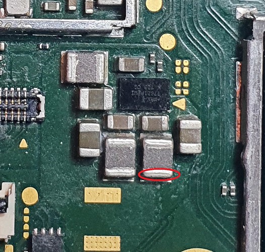
I also found shorts on some components the top side of the CPU board, where few little resistors/capacitors are around the main chip.
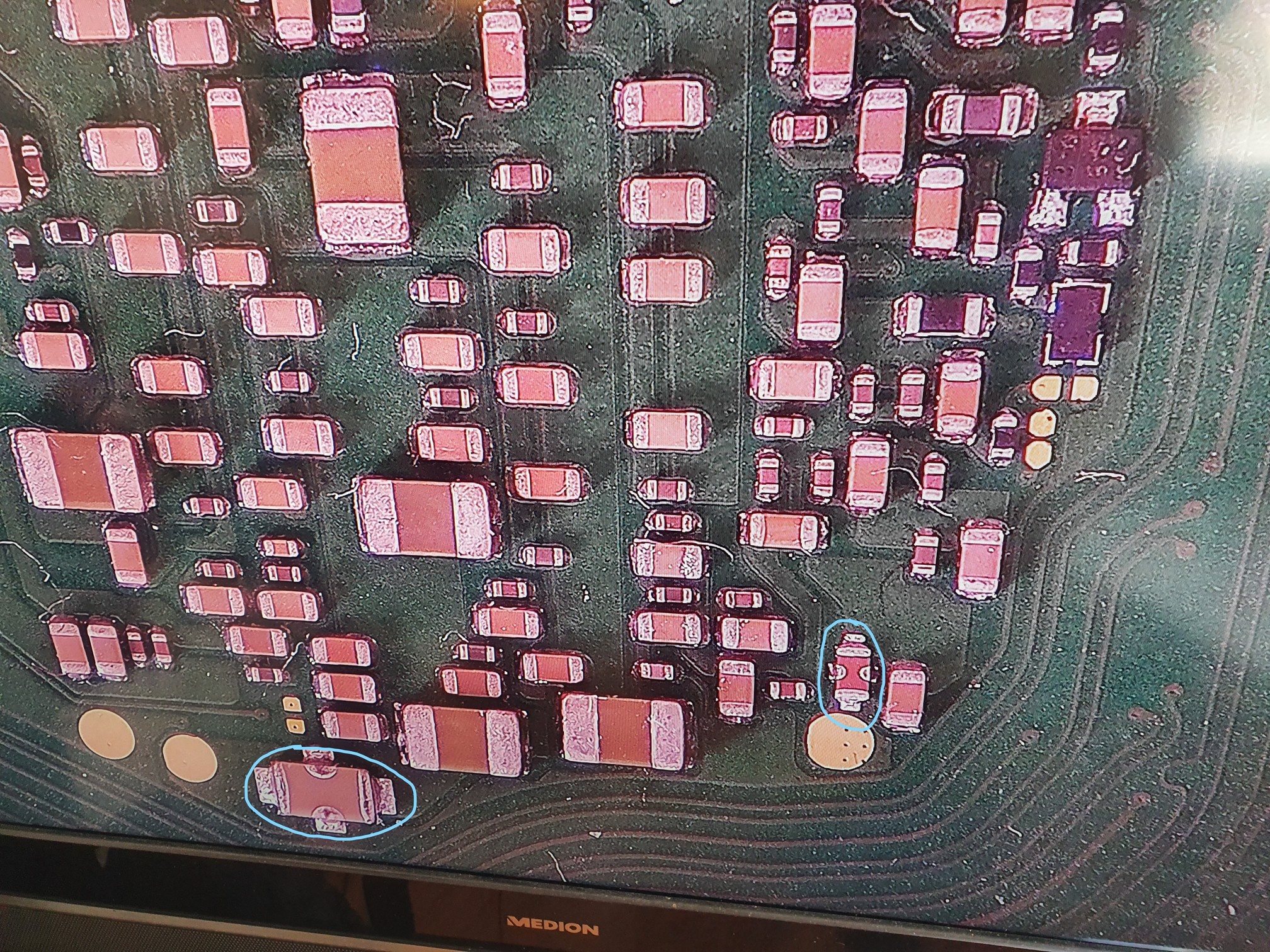
Also, on the following photo (back of CPU), I am not sure what those (blue circled) parts are that have these two additional solder spots on the sides of their “body”, which are shorted to ground too (it’s probably normal, but I am not sure). However some of the solder there looks as if it has been melted before, maybe the previous owner put it in the oven or something ^^
Caps below SoC connect to earlier measured rails, these critical rails are short to ground (red, yellow) hence why some of the caps etc are measuring short.
It’s an inductor btw, almost looks glittery, that’s the ferrite.
I would have expected the output to be enabled while attempting to boot linux and a voltage present at the highlighted point, you could check this on another switch.
Tbh i think it’s more likely to be Ram or SoC… but the Mac IC is easier to remove
ok. I think atm I will not attempt to repair this. I was thinking to start with something a bit easier. Maybe I’ll get to this sometime in the future; if so I’ll continue this post.
Still I’ve learned a lot already through diagnosing and attempting to fix this console, which is amazing!
I wanna thank you guys for trying to help! Especially @Severence, you put a lot of time in it. Appreciate it mate!
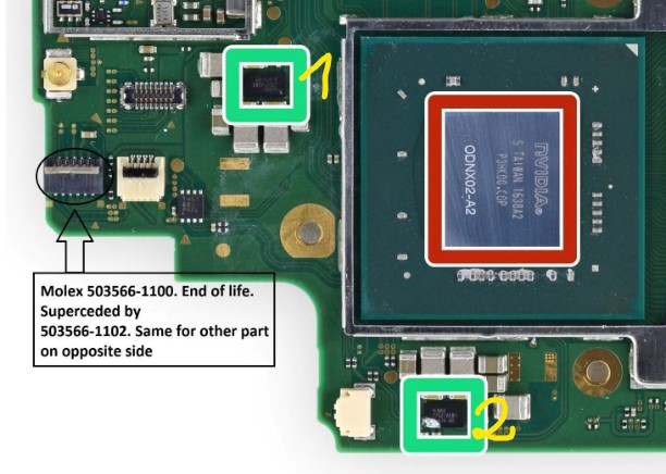
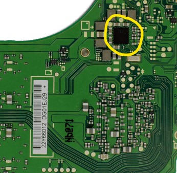
Hi, thanks for your reply, SherriffBuck! I’ve been doing some reading in other posts and assume that with “GPU buck” you mean one of the ICs controlling the GPU, is that right? Could you point out which one are you referring to? I’ve attached two screenshots of the places that I think might be the ones, all pointed out in yellow “1”, “2”, and a circle. As I already pulled the IC on position “1”, that one is proably not the one you are talking about, but just double checking here.
Hi, this is already ages ago, but I’d like to give an update here:
Removing the two Max ICs (the one I marked 1 and 2) didn’t clear the short.
I finally pulled the RAM and SoC, and it turned out the short was gone after the SoC was removed… =) Thanks again everyone who contributed to this post!
 . Also all lines on pins are good. I got 3 switches left all with different faults (some awaiting parts) but I guess being technician and have all tools helps in detection.
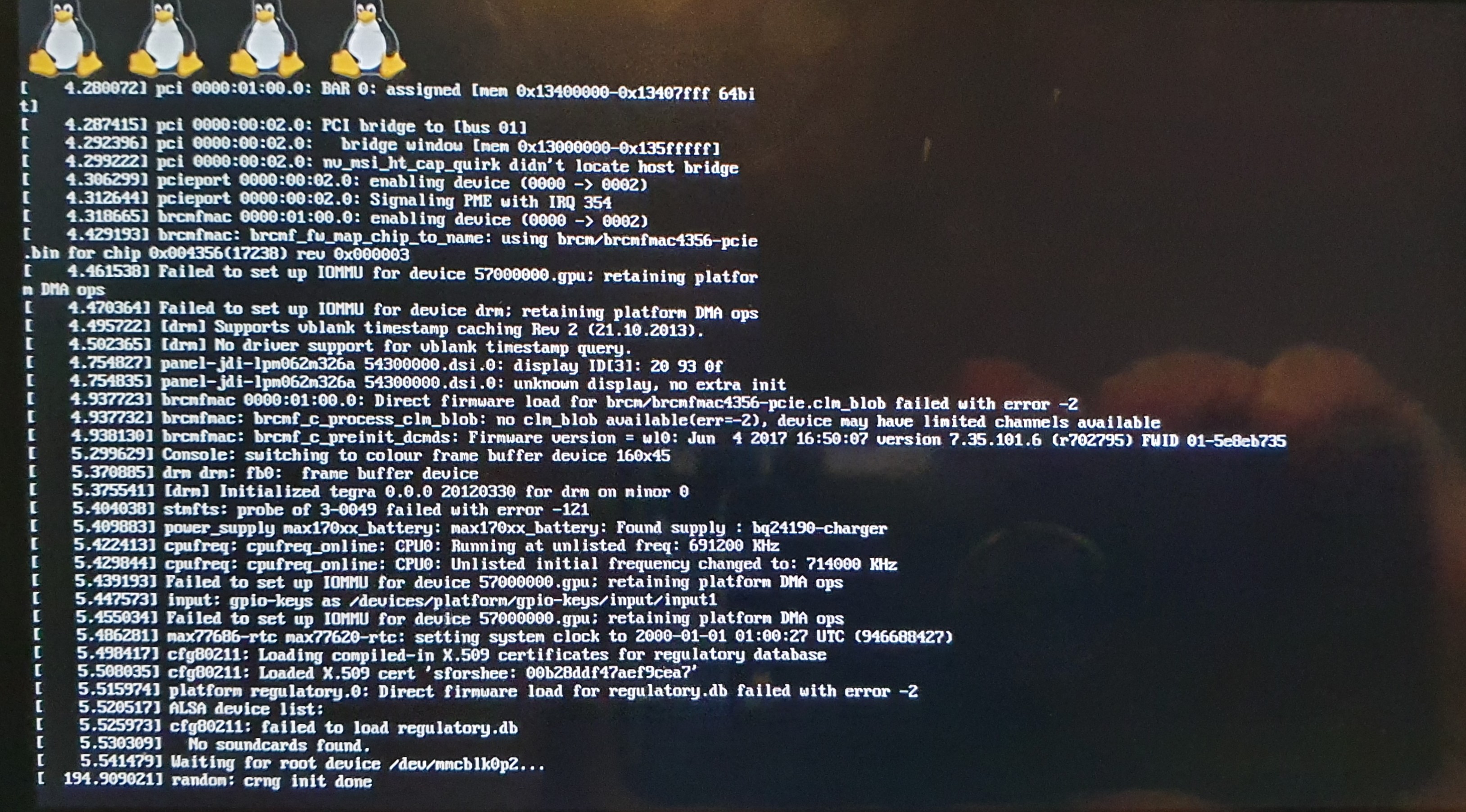
 ) and I found loads of shorts to ground on the back side of the CPU (or GPU? that nVidia thingy… I think the one you call SoC
  ), RAM and other places. Look at this image, I marked them all BLUE (ignore the red squares):