Sorry I’ve not documented anything I’m afraid for OLED, you can use a Switch Lite/Mariko board for a rough reference but there is some minor differences.
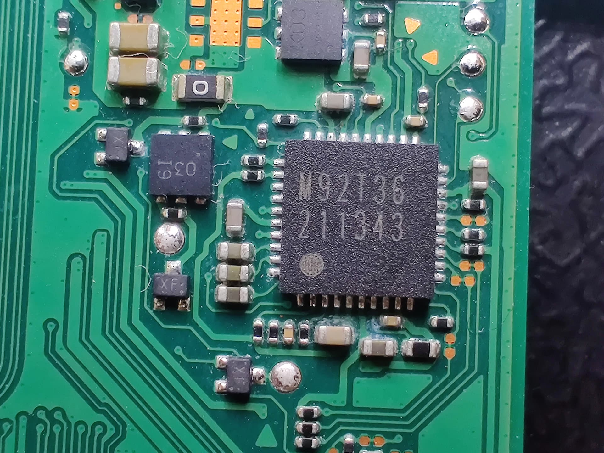
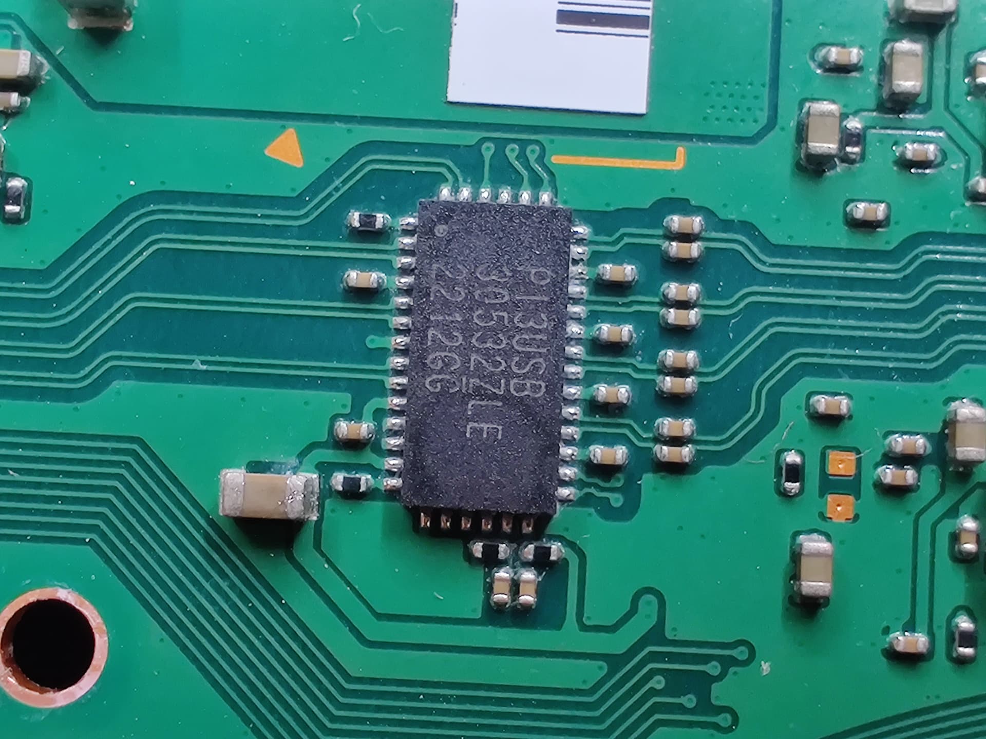
Can you also let me know resistance to ground on 3V3PDR too (most easily found at the large cap by the P13 IC) as well as SYS (most easily found at the 2R2 Inductor near BQ IC)
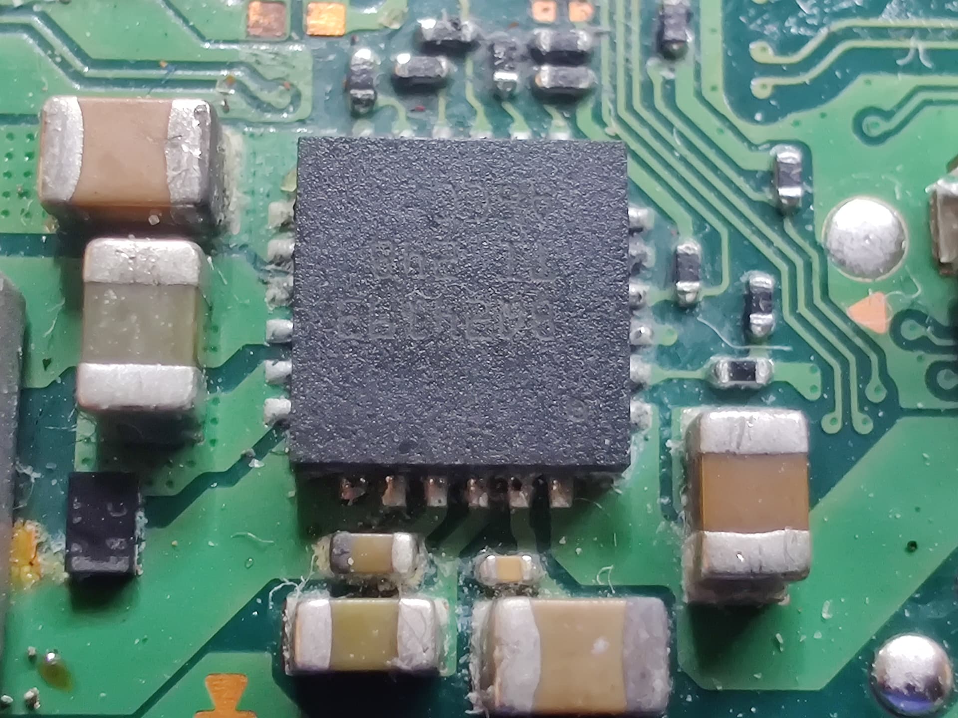
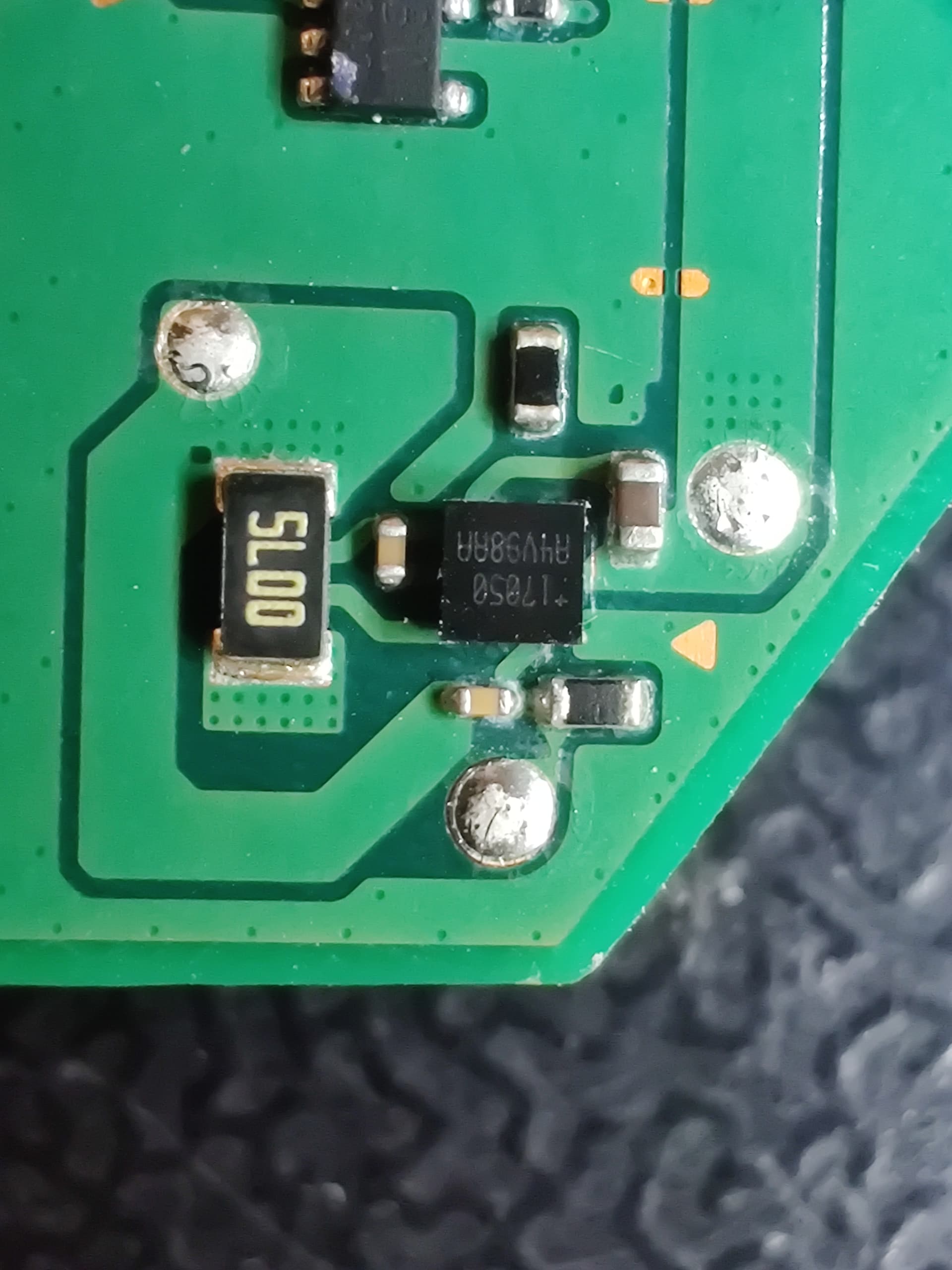
afaict your second image of what appears to be a TI IC which without looking into further appears to be alt 8316 equivelent IC they’re using on OLED’s which on the erista revs etc they used for +/- 5V rails which relate to LCD contrast (afair, though i’m sure there is differences here as a result of this being OLED technology), it would of course be normal to measure a virtual short which relates to the negative rail on the original revs. So I guess the short your measuring on that inductor is normal but I’ll wait for someone who has an OLED handy to confirm my thinking.
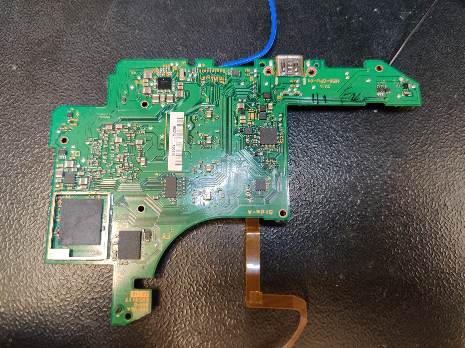
Can you let me know what you’ve done in the third pic, have you reflown things in this area, replaced etc? just asking as i see solder residue and flux here (i need to see if you’ve muddyed the waters further )
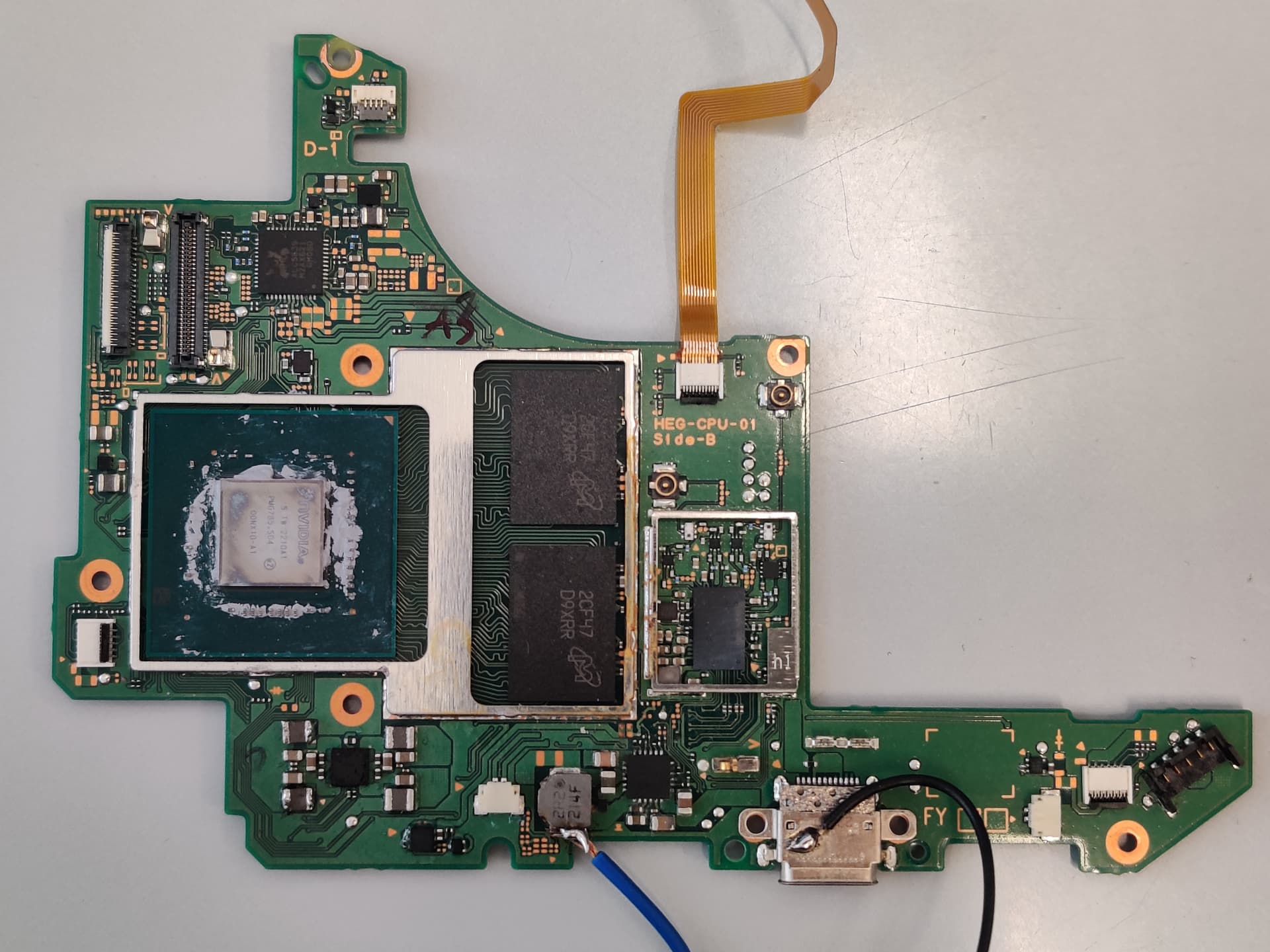
Also, unless the solder on the SOC shield was your doing then it looks as though this Switch has already had a modchip attempt already made. In which case this muddies the water even further I’m afraid.
Can you also let me know resistance to ground on 3V3PDR too (most easily found at the large cap by the P13 IC) as well as SYS (most easily found at the 2R2 Inductor near BQ IC)
Yes, I will measure it tomorrow
Can you let me know what you’ve done in the third pic, have you reflown things in this area, replaced etc? just asking as i see solder residue and flux here (i need to see if you’ve muddyed the waters further )
I removed to two coils on the left to check if I get any voltage from the IC. I put them back and everything is behaving like before
might well just be thermal paste on the shield
I think its just thermal paste (will confirm tomorrow). The heat shields where in very good condition when I got the switch. They didnt look like they were removed before. The caps around the soc are partially covered in thermal paste. I will remove it and send pics tomorrow.
So resistance measurements are as follows:
SYS:
Black: 5k, Red: 222 Ohms
3V3:
Black: 5.27k Ohms, Black: 53k Ohms
The residue on the heat shield was in fact thermal paste. I also removed as much thermal paste around the soc as i was confident in my ability to not rip anything off. I mainly looked at the lower side of caps, since this is where a modchip would be installed (right?)
Nothings jumping out at me with your readings… though, I don’t have an OLED handy to cross reference. Ideally you’d have a donor OLED board to compare and contrast against.
Can you take some clear pics of th BQ, M92, fuel gauge areas and any other area where there was corrosion just incase something jumps out at me, front and back of the board overall too would be good.
If nothing jumps out then I’d probably swap out the BQ IC and then following that the fuel gauge as @jkyoho suggested, just because these two a relatively simple things to do and could cause the issues your seeing if at fault. Save the CPU/GPU reg til last
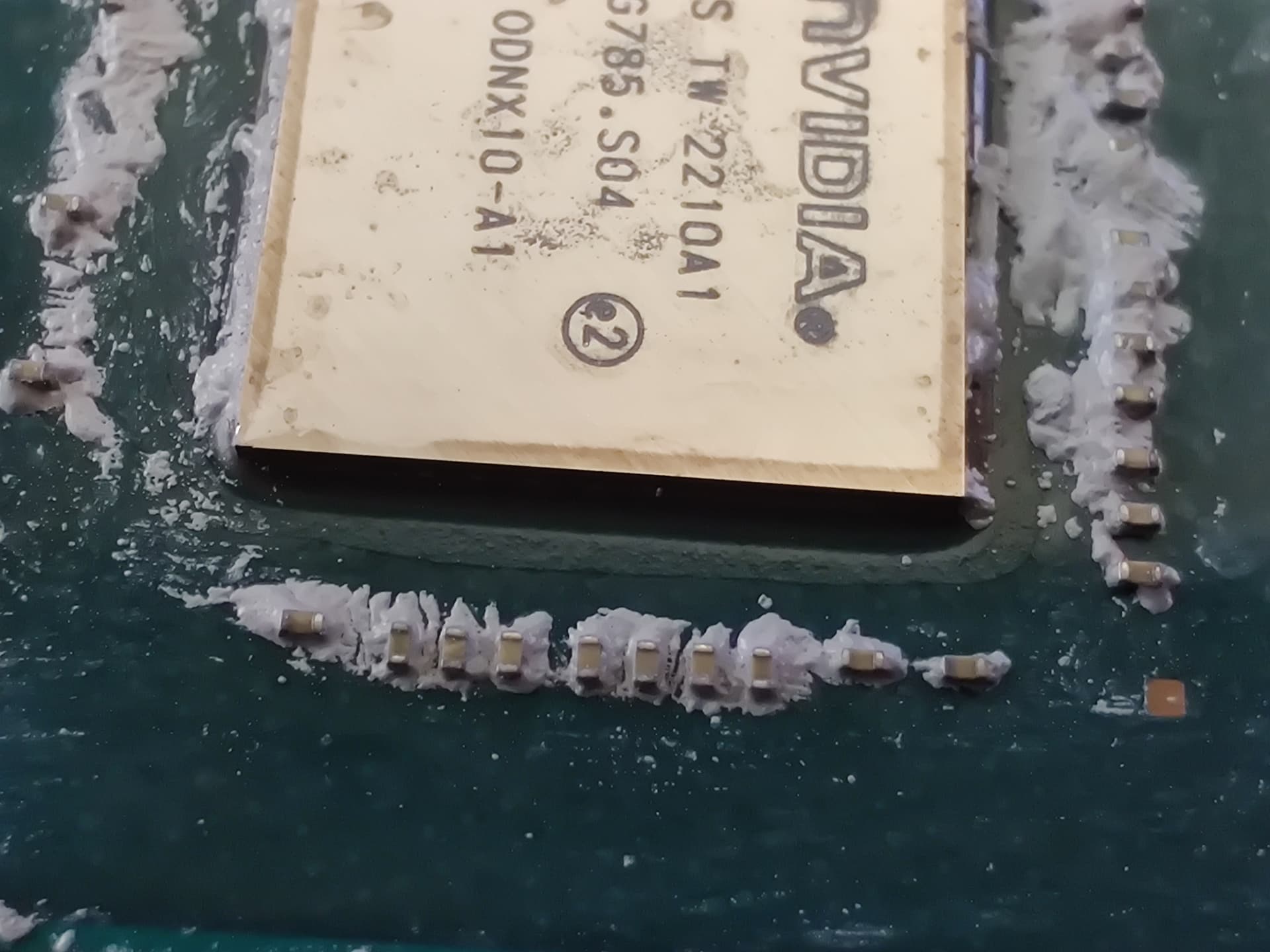
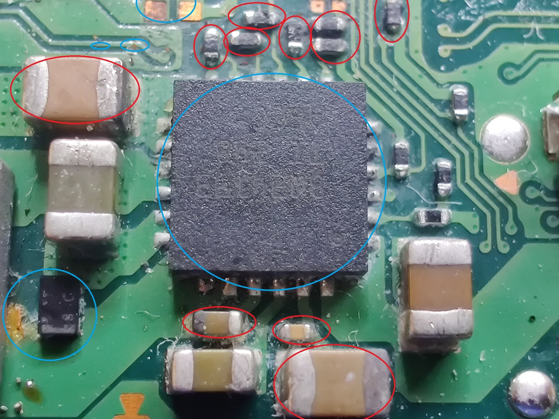
passives in red I’d replace, you can see endcap damige to the passives, while there is a chance you could “recover” them with some gentle polishing with your iron and some flux it’s better to just swap them out to be on the safe side… caps I’m not as worried about but the resistors you wanna swap out for sure. After you remove them make sure that the underlying pads are fully cleaned up and take solder nicely and ensure either side is making it to it’s destinations where possible.
In blue, points of interest / in need of a reflow at a minimum and might be fine, ie. corrosion can be seen and traces need continuity verification
Now In regards to the passives (resistors and caps) , component layout is different here compared to original revs but you should be able to cross correlate by buzzing out in continuity to the IC to see what values you should be using, or, hopefully someone with an OLED board handy can chime in and give you the values.
If replacing the resistors and cleaning up the joints doesn’t resolve your issues as well as reflowing the BQ IC with flux too then I’d swap the BQ IC out and failing that I’d move on to the fuel gauge (though tbh it looks fine afaict) - be sure to shield your connectors nearby when reflowing / replacing BQ IC or be aware where your pointing your gun to avoid melting / damage.
I’d also take a very close look inside any connectors in the surrounding areas for corrosion prior to powering this board up, use your phone cam zoomed in in good lighting if you haven’t got a microscope and make sure none of the pins are green / black etc. (this includes the joycon rail pins too)
Unfortunately I didnt have time to do anymore attempts because I am currently busy with university. But I have some IC that I want to replace and if anything works I will report here.