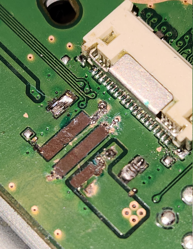
I’ve regretfully ripped off the fan connector from its pads during a routine clean.
The damage has caused the PWM via to no longer be useable.
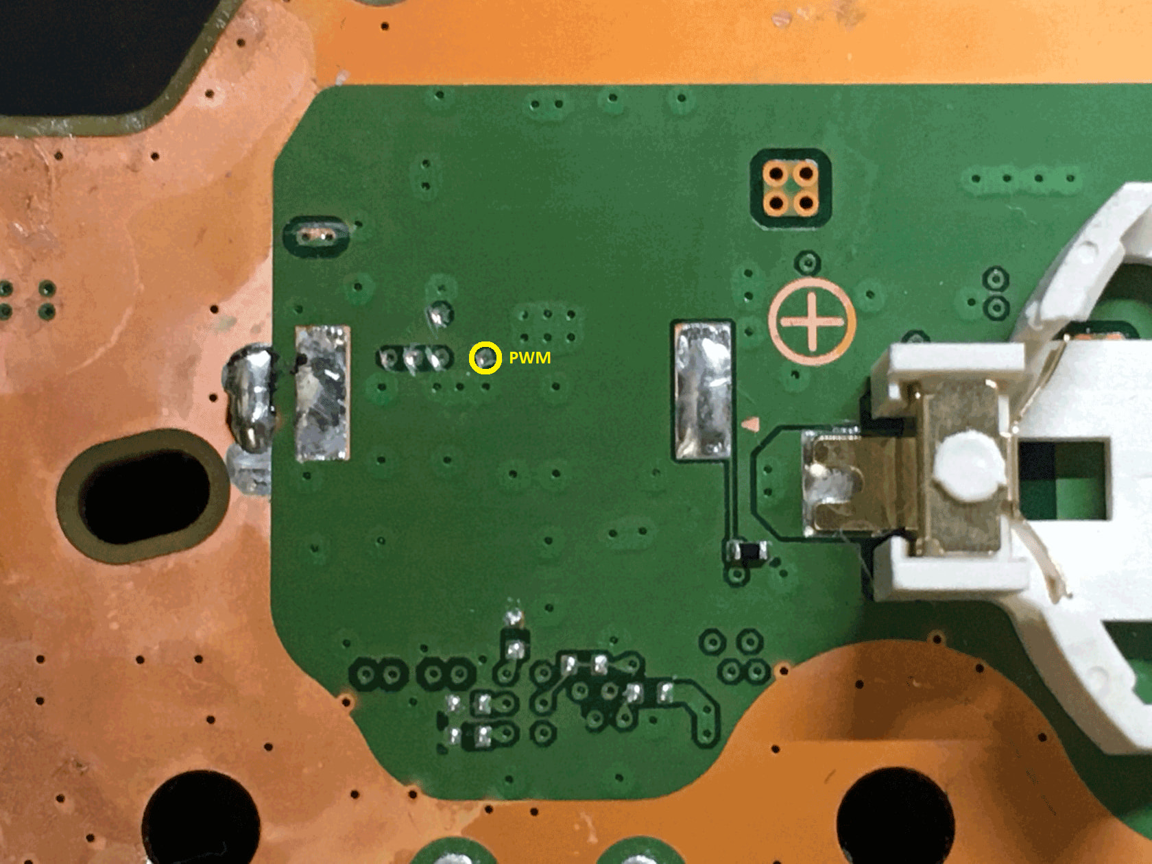
I’ve done some research online and found a lot of alternative PWM trace points for US motherboard configurations but none for the 1202A (1200 Series).
Ideally it would be better to not have to run a 0.1mm enamelled jumper wire form the bottom of the motherboard to the top however, as mentioned before the trace on the top is no longer a useable contact point for the PWM wire, but if that is the alternative, then it needs to be done.
Here are the facts:
The PS5 turns on and operates as normal (fan disconnected)
The Fan has been tested using a 9V battery and still functions as normal.
I have a 0.541V (Diode Mode) reading on the pad labelled “1” (suspected alt PWM solder point) https:// ibb. co/ KjY1cNz8
Does someone have any expertise in this field, any help would be appreciated.
I’m not sure what I see on your picture. It seems to me, that there is solder on the surounding ground at the PWM via and towards the ripped pad. If PWM line and ground are connected an alternative point will not help.
The PWM line goes direct to the southbridge. The only easy access would be under the buzzer where the via from the other side is visible under the solder mask.
Thank you for your response, yes it seems that a bit of solder has made its way onto the ground line and therefore won’t be useable for this repair.
Thank you for the clarification of the location of the alternative PWM via on the bottom of the motherboard. For this repair, and for future reference for anyone else facing the same issue, I’m assuming the steps would go as follows:
Desolder and remove the buzzer
Carefully expose the PWM via
Solder a 0.1mm thick enamelled jumper wire to the PWM via
Secure the wire using UV solder mask near the point of contact to avoid disconnection during reassembly.
Connect the wire to the PWM wire of the fan.
As for the 12V and GND i’m planning on connecting it to the top of the disc drive 12V and GND connector, is this method safe? https:// ibb .co / dwv1h3sK
I would restore the three solder pads and resolder the original fan connector. The two mounting points are still there, so it should be relatively easy.
At the PWM pad: a) Use flux and solder wick (and a fume extractor) to remove the solder around the via. And make sure that the via itself has no contact to ground.
b) When the ground and the via are free from solder, I would use solder mask to cover the exposed area around the PWM via. After it has cured, I would only expose the via again and apply solder there. Now a thin wire can be soldered to it.
At the ground pad: Expose a bit more on top and down of the ground layer and solder a wire or a thin solder wick at the missing middle pad.
Expose only at the 12V layer the part around the ripped piece, add solder and add a wire or a bit of solder wick to restore the pad. Make sure that the 12V is not touch anything other than its area.
Thank you for the link to your video, I followed your instructions and after removing the solder surrounding the PWM via, quarantining around the PWM via using UV solder mask, and soldering a 0.1mm wire to the via, I got a strong reading on diode mode of 0.541V.
So yes, as you mentioned, the reason why the fan wasn’t operational when the PS5 turned on was simply because the solder that was on the PWM via was also bridging onto the motherboard outside of the PWM trace line. But after removal of the solder that reading went from 0.000V to 0.541V.
The fan connector housing was soldered back onto the board no problem and the fan now fully works!
Also made the most of the disassembly to redo the liquid metal, and clean the heatsinks and she now runs a lot quieter and cooler. Good as new. Keeping it in the horizontal position from now on, hopefully that will extend the liquid metal’s cooling capabilities for a lot longer.
grinding off the surrounding ground pad near the PWM from the connector side is more easier than running a jumper under the buzzer from the other side. Try that next time
@jkyoho You’re right, It is definitely easier than running a wire from the buzzer PWM via on the underside of the motherboard. But wouldn’t you want the surrounding ground pad around the PWM via to be as untouched as much as possible for this repair?