Hey all Thanks in advance for looking at this post, I’m fairly new to repairing electronics and this is my first ever attempt at repairing a Nintendo Switch.
I bought a Nintendo Switch for £50 off Ebay, stating it didn’t power on and they had no idea what was wrong with it as it didn’t power on nor did it charge. I’ll list my findings below in some sort of order and hopefully that will help you see what I do
The Amp Meter was showing 15v 0.16a, but then went to 15v 0.46a. The battery that is in there shows a voltage reading of 3.90v, and steadily rises. However, this also drains quickly when I take out the charger. At this point there is still nothing on the screen.
I replaced the battery to start with one that was reading 4.0v fully charged. I still have the exact same issue, so I have ruled out a battery issue for the time being.The Switch shows 15v from charger to the point above the charger.
I took the board out completely and gave it a good clean with IPA as there was some clear water damage where the card reader was. There was also a bit of a battery leak that came off very easy with IPA.
I then tested for shorts around the board in the common places. No shorts from ground around M92 chip, BQ charging chip or P13USB (using the shielding just to the right of the CPU or the screw). There is also continuity on the Coil, however it was a bit dirty before I cleaned it up and it wasn’t making a solid connection with continuity but now it is.
When I’m charging the Switch, two capacitors surrounding BQ charging chip AND the coil itself get very hot quite quickly. Also to note, if I place both probes on either side of these two capacitors, I get a short for around 1 second then it goes (I thought if it was a certain short it would stay beeping).
Voltage to the battery connector itself when there is no battery plugged in reads 4.1v (which I think is normal for the charge circuit).
I have now purchased the following: M92 Chip, BQ Charging Chip, P13USB Video Chip and a new Coil (Inductor I think?). Bought two of everything just in case I mess something up! Does anyone know if I should replace any of the components and whether that would help?
Thankyou again for reading. Hopefully the information I’ve provided is enough to help me try and get this resolved
P.S I should also add that I am more than happy having this as a donor/dead board. From what I have even learnt so far, the price is more than worth it
In future, avoid powering the console until fault conditions have been resolved. Validating fault conditions are resolved involves checking all primary/critical voltage rails, of which I’ve detailed and can be found searching the Switch category.
In future, I would avoid cleaning everything up to begin with, liquid damage/corrosion is you clues and cleaning it all up prior to documenting anything could result in you fixing one fault but unable to find another, it’s a bit like taking a pressure washer to a crime scene Take photos of the board which may serve you well later, and deal wih each corroded area bit by bit, once you’ve verified you’ve aliminated all liquid/corrosion and resolved the underlying problem you can give the board a good scrub
Just making sure, but ensure you disconect battery power prior to measuring continuity/diode/resistance. If that’s the case, you likely have a short on your SYS rail and BQ is likely at fault, instead of using continuity set your meter to resistance mode and place one probe on ground and the other on one side of the 2R2 coil near the BQ IC and note the reading.
Start by removing the BQ IC and note the reading on that coil again, if it was shorted before then ensure it is now no longer with BQ IC removed, if so put on the replacement.
I doubt this, the only feasable way would be if it was pierced, or had swollen up, it’s likely was just electrolysis, and I’d imagine the battery itself is fine unless the fuse in it has blown
Also, check the LCD connector pins, if the unit had been opened before and the person prior had no experience then there is a very high chance the LCD connector pins have been bent.
So I didn’t get any reading what so ever with the coil, regardless of where I put the positive probe. I tried north, south and to the sides.
After I removed the BQ chip I had the same reading of nothing on the coil, so replaced the BQ chip with another BQ chip. I then lost one of the smaller capacitors I’ve ever seen just underneath the chip.
(It won’t let me attach a picture to show you )
The sides of the capacitor came off which I’ve never seen before, and don’t know how important it is. The new chip was soldered on okay after trying a couple of times, and there was no shorts around the area once the new chip was in place.
I have also replaced M92, again that seems fine with no shorts anywhere on the board. Also, P13USB is okay as well.
I now get 15v 0.1a when the unit is off, however when I press the “On” button, the amps go up to 0.8a so clearly it’s trying to do something.
Any ideas? I’m documenting this whole process no my YouTube channel just in case that was easier!
Hmm that’s strange, sometimes there is a good layer of dried flux here which will prevent your meter from getting a reading. If your meter is manual ranging, set it to the 20K posistion and see if you get a reading, or try reversing your probe polarity, I forget which, in one polarity you get approx 10K which is normal.
Think after a couple of posts the function is unlocked, when it is I’ll let you know what the capacitor value was.
It’s pretty typical for passives endcaps to seperate in liquid damage cases, this capacitor was likely causing trouble or would have caused trouble if left so it’s probably a good thing it came off
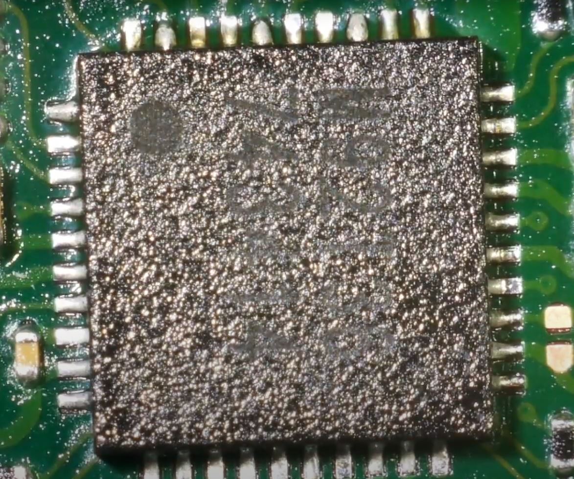
Sounds to me like when you hit the on button the console is booting. Normally the USB would prompt the console to boot too and if it’s not, it’s typically as a result of a bad USB connector or bad M92 or bad soldering on the M92 IC, tilt the board at an angle and inspect the joints around this IC and see if any are lacking.
Also, try the USB in both orientations and see if the console boots then fast charges in a certain USB orientation, if it does then it might be pointing to a different issue.
I take it your not getting anything on the LCD at this point either? if yes, double check for any bent pins in the LCD connector, if they’re fine, then take a close look at the backlight and LCD ribbon traces/pads and ensure there is no breaks or errosion, pretty common in liquid damaged cases for this to happen, particularly the backlight ribbon.
I have done this without the battery plugged in, by putting the red probe on ground and black on the coil and it shows a reading of 5.05 - Not sure if that’s any good?!
This is the capacitor… to confirm it’s now completely missing
Well, as far as I can tell it is a bypass capacitor, and is in parallel with the larger one below it, so I would be surprised if it stopped it from booting.
Reading it all through again, it sounds like it is working. I would take a very close look inside the LCD connector to see if any pins ae out of place (pics would be good!). Does the backlight come on?
I will watch your two vids and see if anything comes to mind.
Ah ok, I have now watched the video and see it was 0.01a to 0.08a when turned on. That’s not so good. I wouldnt give up in it yet though, it’s not game over unless the CPU is dead, so there is a lot left to learn from this little board yet!
Given that it changed from a correct slow charge (0.42a) to almost nothing, I would say we need to have another look at the BQ chip. That said, you were in that area for a while, so I would also have a look to see if anything on the underside of that area that has moved. There is a 9pin BGA chip right at the far end that has twice moved around when redoing the BQ chip for me. Once they are wonkey, you need to replace them.
If everything looks in place on the underside, I would have another go at the BQ with your spare.
I am also new to quite new to this, and the BQ has caused me more pain than any other on the board. I think the basic problem is that there are some large pads running into it, such as the bottom left, that are basically impossible to get enough heat into once a chip is in place when using a soldering iron. As such, my current theory is that it is important to get the correct amount of solder on to start with, so that there is no need to touch up in those areas.
Once the chip is off, you need to be able to clean the old unleaded solder off. The best way is to probably mix in as much low melt solder as you can to bring the needed temp down before bringing the wick in. Leaded solder may be enough, but if not some of the special low-melt may be needed). For the removal you will want a large contact area on the iron tip, and have the iron pretty hot. I would say somewhere like 420c, but I have had to go all the way up to 480c on mine before. I guess it depends on the iron…
Once cleaned off fully you need to get leaded solder on the pads (make sure you are using leaded, unleaded requires far too much heat), but without re-flooding the centre pad. Again, I find it difficult on this chip to get enough heat into the board to stop the solder solidifying on the grounded ones. Getting the board warm with the hot air gun may be a good idea, and then using a medium tip on a hot setting to get the pads tinned, but trying not to stay on any particular pad for too long as you dont want them to come off. The last one I did I actually ended up with the middle pad full of solder again but the pins were looking good, at which point I needed to re-wick it all off again - a real pain!
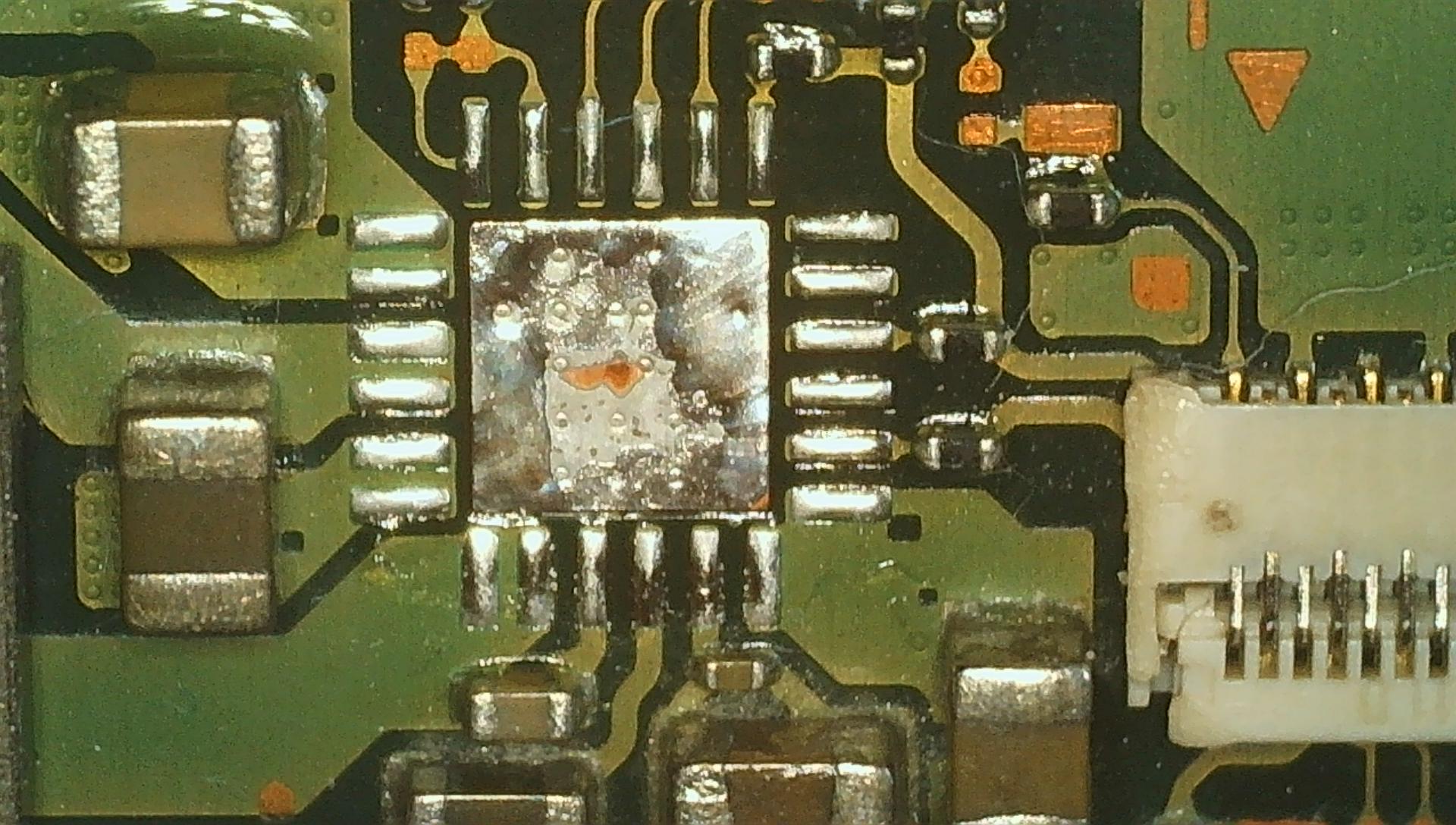
Here is a pic from my spares board that has super-visible traces on it. (s usefull some times, and some of them are really hard to see).
Oh, and for working with the really tiny things, I got these tweezers, and they are easy to break, but really help for things like that capacitor that died.
aliexpress: /item/32970729515.html
You can get the same (probably better) version on Amazon, but for muuuch more.
I’ll just add a few things to supplement Insomniacs post.
Before going ahead and replacing any IC, I would check the battery is not completely flat by measuring the voltage across it out of circuit, the low current your seeing when plugging in the switch board itself could indicate a completely flat battery or a completely charged battery, it could also indicate a blown fuse and also a bad connection between the battery connector and board.
I’d personally recommend you steer clear of using low melt, this area of the board represents the lowest thermal mass and it’s not needed, I see so many boards which are caked in low melt as it has “run away” from them, if your irons is struggling then simply have your hot air assist you, hover it in the area during soldering at 100/150C low air and you will have no issues.
Check your solder, a lot of the “lead” solders from China are not lead but lead free despite what they might say on the label, as a result the solder has a higher melting point and has a horrible grey tone, I can see from your images that the solder is quite dull so perhaps this is the case, would recommend chip quik 63/37.
Found your video Joey, ignore most of what I said above regarding the battery and fuse etc as it seems you already did all that (unless the fuse has blown this time)
I see the situation regarding current draw now, so initially 0.4A then more or less 0A following BQ swap.
Based on the initial symptoms on the coil/BQ getting hot, think your right that that was the original issue, why your meter wasn’t getting a reading to ground I blame your meter these cheap manual range meters are notorious for this behaviour.
Like you and Insomniac said I would go ahead and remove then touch up and possibly even replace the BQ IC once again as there was a couple of pins that I could see which were touching which shouldn’t, I think you’ll find the assistive heat from your hot air during soldering will really help in getting those pads fluffy prior to putting the IC on
Also those components which you thought were fuses near BQ are resistors, from memory they’re 10K, I’d check that the one with the dull end-cap and ensure your getting a reading across it, and I would check it from the pad of the BQ IC to it’s next nearest destination instead of directly on the encaps themselves.
I have also found two capacitors above the M92 chip that seem to be bridging. After having the meter in continuity mode, it shows both top sides touching. My first bet is to sort those caps out and ensure that they aren’t bridging. Once that’s complete, I’ll test the voltage/amps again through the amp meter.
If I still get the same reading i’ll move onto the BQ chip and do what you’ve both said. Are we sure that the small capacitor under the BQ chip (the one that was ruined) will be okay not on the board and that this won’t effect the circuit?
Ok, I have just watched your latest update.
I am pretty sure at this point that the solder you are using isn’t leaded. I would look !not gotta g some good quality leaded solder. 60/40 would be fine.
One thing to note about the switch, is that it will not go above the 0.46 charge with the Emmc removed. It only fast chargesvonce it has booted, which it can’t do with out its emmc abd just goes in to RCM mode.
As it is now, I would be tempted to remove the emmc to force it into rcm mode, and see if a Windows PC will pick it up when connected by usb. It doesn’t need the battery or anything. Have a quick Google for where to find the software, I am on my phone and can’t remember its name.
But with that installed just having it detect RCM can tell us a lot, and if it will boot into hetake you can find out even more.
As you were getting approx 0.4A with the board out assembly and without the EMMC module connected, it’s possible you either have a bent pin at the LCD connecter or elswhere following reassembly or the EMMC module has a fault which brought your 0.4A down to basically nothing when all hooked up
Also, folowing your most recent BQ swap, was the coil/IC still getting hot or is this now resolved?
And agree with Insomniac regarding solder, though my preference is 63/37 as it has a ever so slightly lower melting point and produces shinier joints.
Your soldering iron is definately to blame and not you! you had it set to 450 and it wasn’t even able to melt the solder in air so it was never going to melt it at the board too. I’d look into getting a T12 cartridge style station
Yeah, I ended up buying a “cheap” soldering station as my stand-alone iron was… bad, but I also broke it :D. I got the Yihua 862D+, they seem to be about £70 at the moment, though I think I got mine for about £50. But you should not be in a situation where you cant even melt the solder directly.
 Thanks in advance for looking at this post, I’m fairly new to repairing electronics and this is my first ever attempt at repairing a Nintendo Switch.
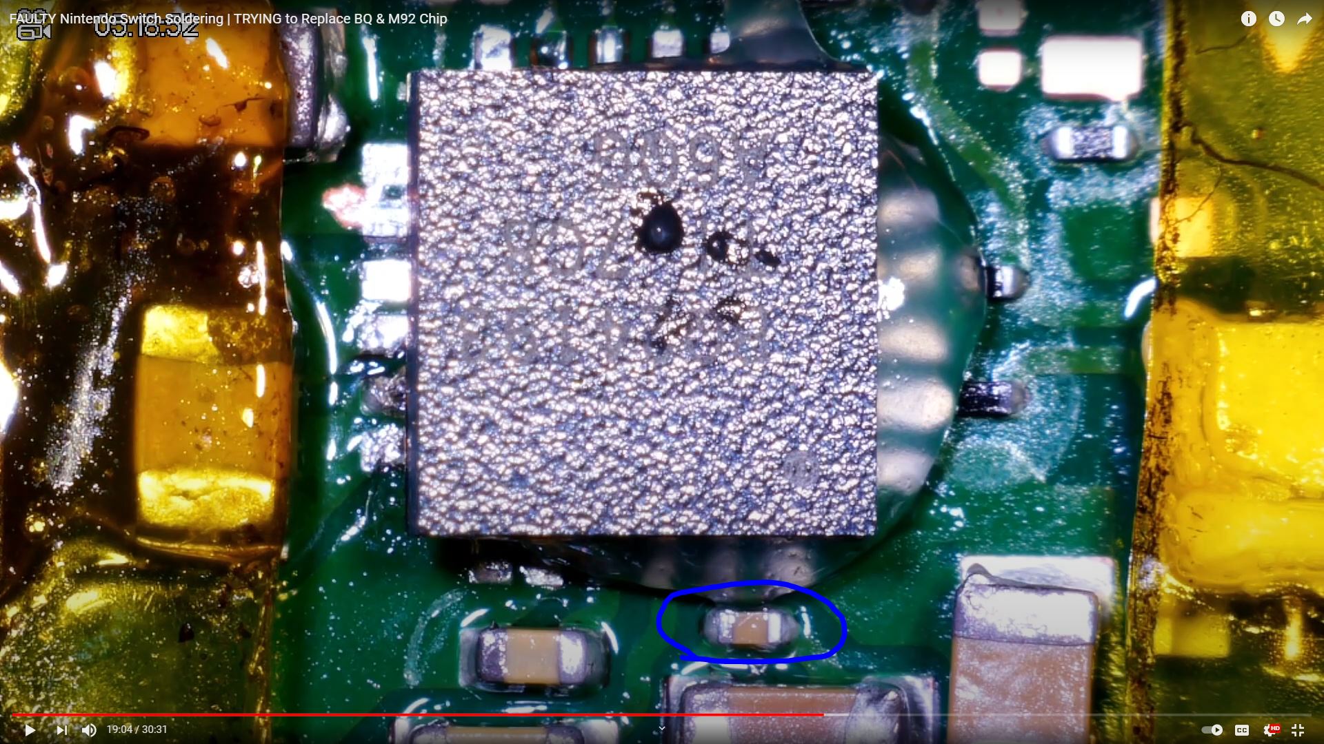
 these cheap manual range meters are notorious for this behaviour.