Hello, so i recently began to work on a 2019 version of the switch which wont power on and doesnt show a charging symbol with const. 0.45 on USB meter. I checked the motherboards for continuity and found these:
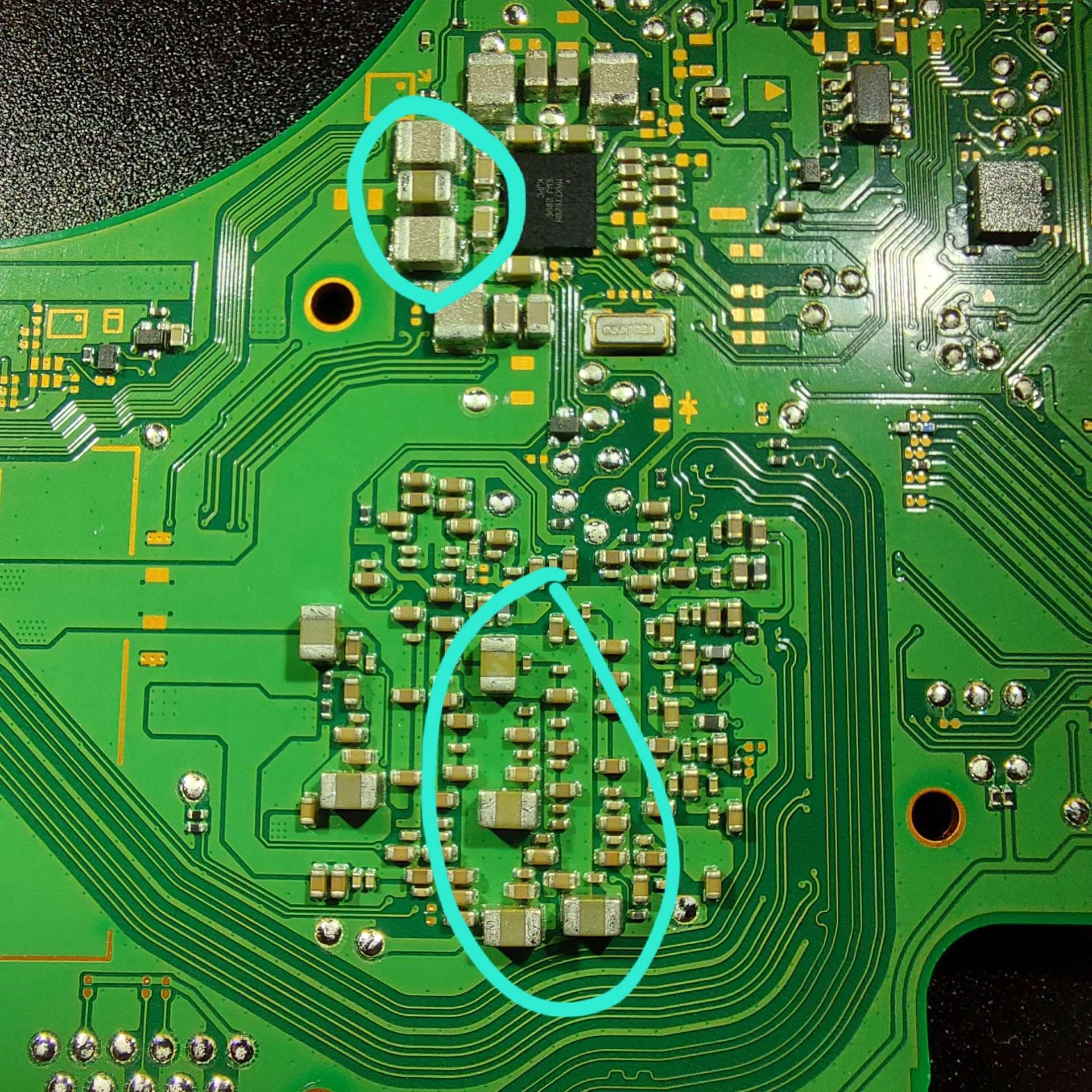
thick blue ones: do beep
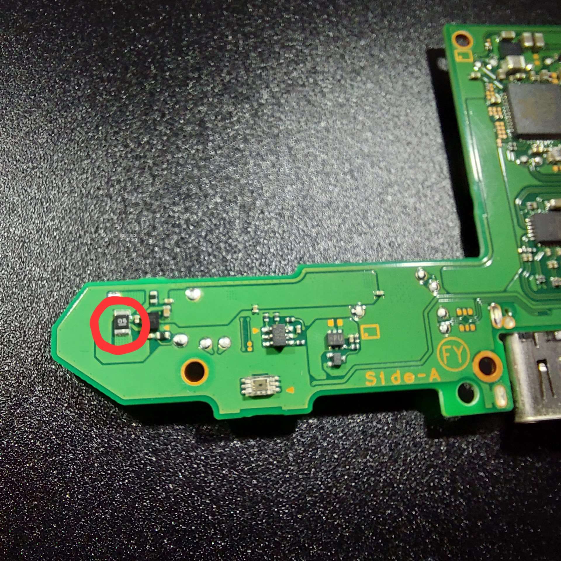
red: what component is that?
I have two new M92T36 chips.
I thought of removing the MAX77620H Chip and see if the shorts are gone but i dont really know how to tackle this problem in the right way.
Top blue are a low impedance inductor on top, a low impedance cap in the middle, follow by a similar inductor on the bottom. Middle of the board are a passive array directly attached to the CPU so most will most likely be very low resistance.
.48a braindead scenario could be a multitude of things. For instance, the BGA IC next to the red circle is the fuel gauge. It tends to be fairly fragile and if dead will prevent the system from booting. You could probe the capacitors to the west and south of that IC to check for shorts, if you have a microscope you can check the balls to see if any may have merged or cracked.
If you’re successfully negotiating 15v and see a constant .4a or more, very good chance your charging circuit is just fine and m92 / bq won’t need replacement. Doesn’t hurt to probe the M92 caps if you haven’t already. The south east cap on a switch board is directly connected to the CPU I believe. While not always the case, if this one is short you most likely have to reserve this board as a donor. You could also probe the cpu and gpu bucks which are on the south and west of the board and check resistances there as well, although much like the other max chips some of these have low impedance so don’t rely solely on the beep of your meter. Actually check and record the resistances and compare to known good values. I do believe if either of these IC’s are faulty, your system will not boot.
Lastly, with battery removed, you could plug in a charger and test voltages around the board to see if the needed voltage rails are present around the more common fault areas. There are tons of posts here covering this, so spend some time digging around and you’ll find out where and what these values are.