I was repairing a Switch that I believed had a bad charge port. Everything worked great on it, and it charged just fine, but wouldn’t dock to the TV. In my limited experience, that can be a bad USB port.
I replaced the port, and it seemed to charge fine but again, wouldn’t dock. I rechecked it and realized when I flipped my cable over and plugged it in, it stopped charging. Flip it back over, and it charged again. So I figured I had a faulty replacement port, or I didn’t get the solder hot enough to flow and make a good connection when replacing.
So again, I replaced the charge port, and this time it charged both ways, no problem. But it still wouldn’t dock. Then it shut off and wouldn’t start back up. I checked amperage again, and now it won’t fast charge, it’s stuck at .44A. Tried it with a known good battery same result. Won’t fast charge won’t boot.
Unfortunately, I don’t have anyway of checking shorts in the caps. I’m very new to this and am still building my tool set.
But any suggestions? I was thinking of replacing M92T36, but honestly I’d just be guessing if that’s the issue. I know Steve said in his videos he hadn’t figured out how to fix Switches like this, but it was just working. I can’t figure out what could’ve happened to brick it now.
I don’t have anyway to check continuity unfortunately. But I think I will go ahead and replace the video chip as well as the charging chip. Can’t hurt anything.
I would check before replacing. If you have bad connections on the usb c port it doesn t make sense to change a single chip. If you don t have a breakout board you can disassemble your dock and use the usb c plug and the ribbon cable for testing continuity threw the port.
Sorry for my ignorance, as I’m new to all of this, but how would I use the dock USB Plug and cable to check the Switch USB Port?
I know how to disassemble the dock, as I’ve repaired a couple of them, but I’m not sure how to use it as a breakout board.
Also, I doubt it’s the USB Port, as the battery is good and charged, and the Switch still won’t power on at all. I would think with a bad USB port it would power on with a good battery.
My concern is if maybe a couple of the hidden pins got cross soldered it caused a short or something in the board, but I really don’t think anything is cross soldered.
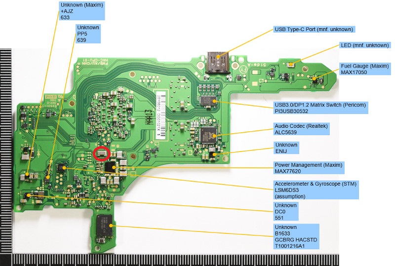
I’ve been looking for this case too. Yesterday i found a thread in other forums that state he successfully revive the board from 0.4A case. All he did was to remove the crystal/oscillator in MAX77620 PMIC area, because when he tried to measuring it with scope there’s no oscillation on it but when he measuring it on working switch there’s an oscillation. Crystal/oscillator function itself is to synchronizing two sections of the board to the same frequency, so if this part is faulty there’s gonna be some kind of error in the board, well to be honest i haven’t tried this because i am still waiting for the capacitor that i lost, once i get it i will try it, and i can’t guarantee it but it’s worth a shot since there’s nothing to lose anyway. Noted : if you want to remove the oscillator take note of how it was mounted before in case you want to put it back. Red circle mark is crystal/oscillator