Hi,
Problem: When battery discharges below a certain percent (switch turns off because it ran out of battery) it won’t charge back up. I can however charge it if it hasn’t run out of battery. So I essentially can’t let my switch completely discharge or I can’t charge it.
Background: A long time ago I put in a Trinket M0 into my switch and removed it shortly after. In my inspection of the board everything looks good, but if you would like me to take readings of parts let me know. It almost sounds like a resistor or capacitor is damaged, but I don’t know enough to know where to begin to look for this specific problem. If possible I would like to avoid changing out the charge chip as I don’t have a solder rework station.
As a temporary solution I bought an external battery charger for in case it drops below the voltage the switch is willing to charge it at.
It is more than likely to be the BQ IC. You could take a photo of the Hekate battery stats page to further confirm or deny this and also a photo of your board in this area
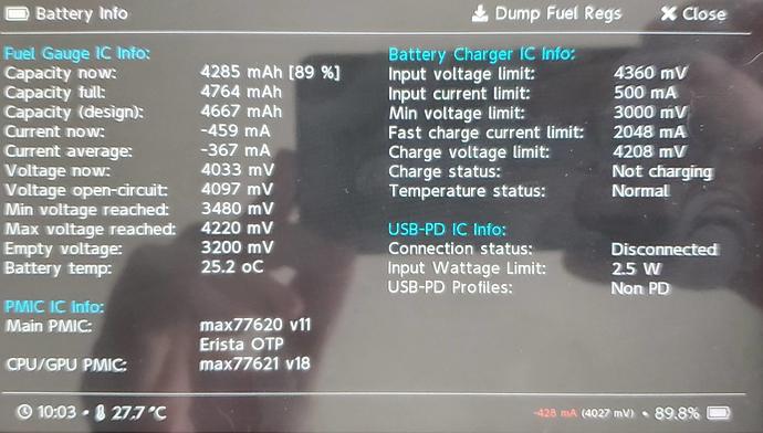
I was hoping that wasn’t the case as I only have a heat gun that puts out a ton of air so it is not good for removing and reflowing chips. A picture of the fuel stats in hekate is included below
I could not include fuel_gauge.bin, but I believe the info is included on the left. Let me know if you still need me to open it up to get a picture. I try to avoid doing it too frequently as 2 of the screws are stripped and I don’t want to make it worse.
Can you take a photo of that same screen with the USB/AC adapter connected also?
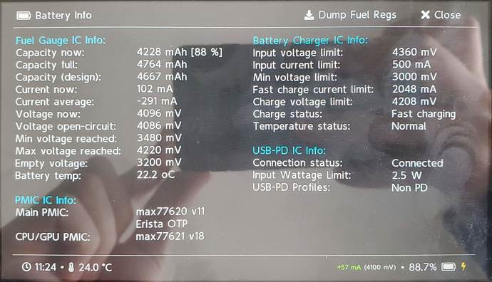
Sure. Here is one with it plugged in.
hmm Hekate’s indicating only 57mA. (which may be normal depending)… do you have a USB Ammeter? how are you powering, USBC cable or AC adapter?
Your fuel guage looks fine btw.
I am using my computers USB C which only provides .5 A 2W power. If I do it with a fast charge AC wall charger I can get 1 A to 1.4 A. That goes for both with the USB C ampmeter as well as what’s shown on hekate.
Which would imply BQ is functioning normally (or at least partially) I’ll have to go over the datasheet to see how it behaves when below threshold voltage scenarios.
Are you sure this isn’t a misidentification of fault… for example, battey undercharged and in autoRCM preventing you from seeing indicators on LCD etc. If your unsure of this, temporarily disable autoRCM (if it’s currently enabled) and intentionally discharge the battery and then plug USBC in with ammeter, a reading of <0.4A which is normal until threshold is reached etc…
AutoRCM isn’t enabled and I have left it charging on multiple chargers overnight and it still wouldn’t power on or be recognized by TegraRcmGUI. I do find it very strange behavior. I have a adafruit charger to charge up the battery at .1A and after 4 hours it was at 10% where I could charge it normally over a few hours to get to 100%. As long as it doesn’t power off because it ran out of battery I can charge it.
Yeah very strange, I’ll look over the datasheet tomorrow and see if there’s anything in there that could potentially cause these symptoms.
When the battery is fully discharged, what is the current readout on the ammeter once the consoles plugged in?
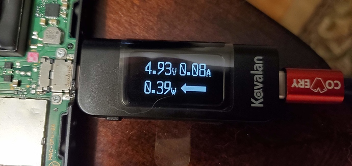
When the battery is fully discharged it acts as if there is no battery connected. Attached is a picture of the readout when it is fully discharged and the switch won’t power on.
Approx 0.08A indicates either a completely charged battery or a completely dead battery, IE: no charging taking place and the current is being drawn by the board itself.
It’s possible the center pin on your battery connector doesn’t have continuity, if you disconnect the battery and check it’s making it to the obvious testpad in front of it. You might also want to check the corresponding wire on the battery itself, it’s not uncommon for these wires to sepearte under the sticker after a lot of handling.
Though i will say i don’t recall the symptoms of not having this line continuous… but according to the fuel guage datasheet. it’s
Auxiliary Voltage Input. Auxiliary voltage input from external thermal-measurement network. AIN also
provides battery insertion/removal detection. Connect to V BATT , if not used.
So i suppose in theory you could bridge the center pin of the battery connector to V BATT (two battery connector pins left of it )as a test…but at your own risk. (see if the current draw on the ammeter goes up)
Though you might wanna grab those photos of your board prior.


