I have this Switch v1 that I’m trying to fix (purchased on the French equivalent of eBay, so… pretty dodgy). When probing the USB port in diode mode, some readings were wrong. So I removed the port, and that’s how I realized it had been worked on before. Most pads had been ripped and replaced with wires and solder mask. To be fair, whoever worked on it did a pretty good job.
After removing the port, a lot of readings were still wrong. Turns out, some filters, caps, and P13 were dead. I changed them and most readings came back to normal apart from D+ (open) and D- (shorting to ground).
I followed everyone’s advice on this thread here https: //www .tronicsfixforum.com/t/datalines-d-d-show-ol/5839/5 . I can’t remember whether it was @Calvin or @Severence who suggested to check continuity across filters and on the back of the board. Filter was fine, and following the tracks across the layers, it led me to the SoC. So I’m guessing the data lines on this one won’t be repairable. Nevermind, it’s still technically usable without it.
I tried booting with a charged battery. It kept crashing after the first logo. So I changed the fuel gauge and it booted fully (and there was much rejoicing, yay).
I fixed some traces on the USB port, chucked a new one, and tried charging with the adapter. It instantly shut down the Switch. My ammeter was reading 15V, 0A.
I had to unplug the battery to revive it. I assumed it was maybe M92 ou BQ, as it is charge related. I changed them with “new ones” from Aliexpress, so not 100% reliable. However, it didn’t work.
Aaaaaand it failed again (I think). It’s not charging any longer. It still displays the charging symbol, it still docks but only on one side.
Should I try yet another M92 chip?
First thing I changed, as it wasn’t booting at all in the first place. It’s however possible my soldering was bad, as I didn’t properly reballed the chip. Since there are only 9 pads, I assumed I could get away with only tinning them.
Yes please pay attention again ;)maybe the resistor or cap is faulty. If you can use hekate you can see the informations about charging in the tool section. Maybe you can find there the more infos.
I wish I could, but since the data lines are blown, I can’t. Which is a shame, of course.
To be honest, I’m not sure it’s going to be the fuel gauge: it’s rightly displaying the percentage on the Switch and the charging symbol appears when plugged in.
They look fine under the microscope, and I’ve also tested them on the breakout board.
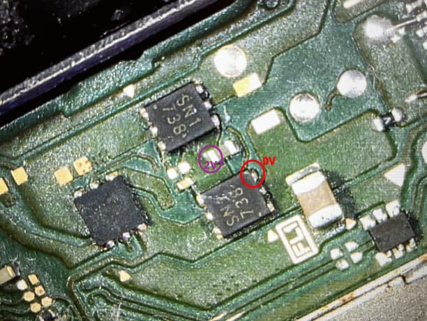
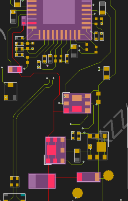
What if it were the FETs, though? I have the right voltage until the first FET, but on the plane between the two power FETs, I get 0V. What do you think?
Everything looks fine… and everything was working fine this morning, drawing a healthy 0.47A… until just right now, where the current draw is all over the place, going from 0.00 to 0.04, up to 0.47 again…
The overall charge went from 20% to 44% in about 40 minutes (that’s when it started behaving strangely)
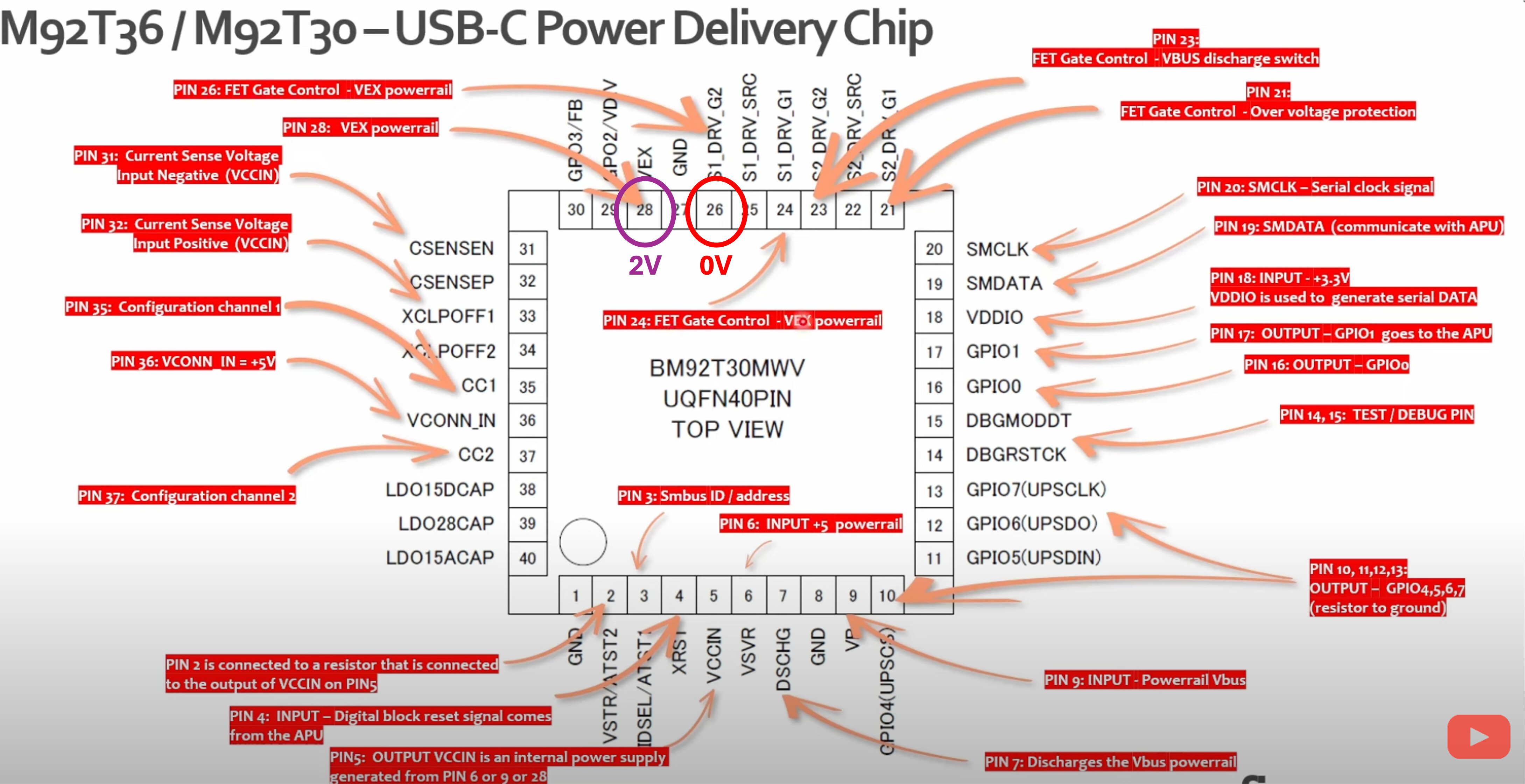
VEX is faulty, the gate pin is at 0V, so everything seems to be pointing to a faulty M92. But what do I know…
I have a few chips coming, so I’ll swap it again. Hopefully, it’s not going to die instantly.
Yep, everything on that red line is present, so no fault here. The gate on the FET on the right hand side has 7V. The gate on the left-hand FET has .4V. So I’d bet against the M92T36 chip. As soon as I grab replacements, I’ll give it a try.
Hey there,
I finally got the new M92s.
So I reballed the fuel gauge, just in case. Nothing changed.
Then I changed the M92 chip, and now it seems to be working.
Thanks for your help @RedScorpion!