Thanks for looking at my post , I have a question for anyone who can help
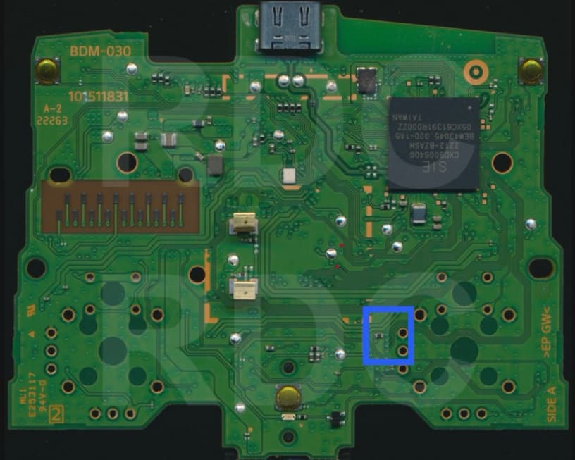
The component in the blue box pictured is it required to be on the board ? mine is missing and looking at another post I have identified it and can replaced , the reason I’m asking is because I have severe bottom right diagonal stick drift on this controller (when powered on the right stuck is permanently stuck in the bottom right diagonal position)and I’m wondering if this could be the cause ? If anyone has any ideas they would be very welcome
joystick movement related to the voltage output from the X and Y axis potentiometer, ranging from -1.8v to 1.8v I believe. If you have a static, non moveable direction, you better check if you have torn broken pads on the joystick when you remove the old one or broken traces around. I don’t think that resistor is related to joystick but missing any component on the board would/might lead to malfunction of the controller for sure.
If you want specific answer on your project, try to upload the clear, detailed picture on the actual not working controller pcb you working on, instead of a picture online in general.
I received this board damaged already i noticed a trace damaged by this resistor/cap , I scraped of the via next to it and replaced the trace , the cap is not on ad I was hoping to get away with it not being there , I get continuity from the via to the pin , I believe the cap is not needed and there might be another issue ,
I will try and upload a photo when I’m back home later but this isn’t the easiest to do here as I have to use flickr as I can’t use imgur any more
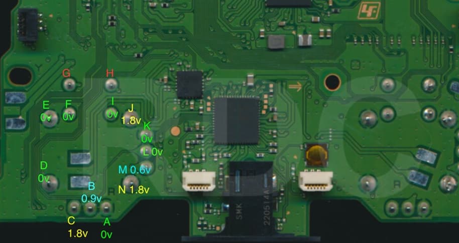
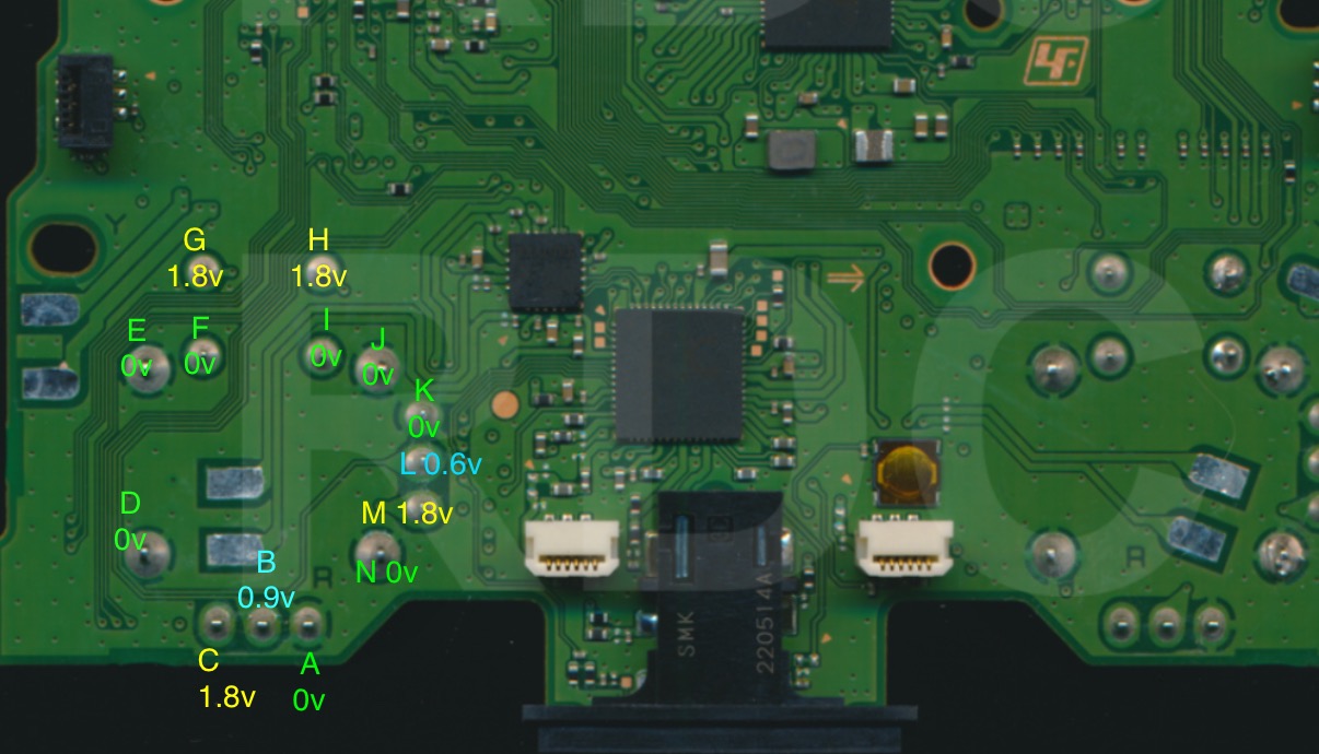
I really appreciate your help with this matter and have taken some voltages that I’ll add here too I’m not sure they are right so you might be able to tell me if they are incorrect
I misplaced some of the voltage readings , I was rushing the other night. 0.6v seems low could that cause the stick not to be centred ? On the other one I get 0.9 which is higher should they not be the same ? Does the voltage regulate the centre of the stick , being too low is it pulling it away from the centre ?