Sorry bud, must be thinking of someone else 
sorry for the silly question, but : jig = stencil ? 
No a jig is effectively a fixture or clamp (the bronze coloured one I linked to is a jig), IE: what you’d hold the IC in to keep it in place, a direct heat stencil doesn’t require this aside from slight downward pressure from tweezers
ok, the thing i called “holder” Haa, those non-native English speaker what a pain haha 
Hi there,
coming back to this console, as i finally received my MAX77621 ICs i restarted to work on this console (i also orderd stencil as we discussed, it got lost by logisitics, i will have to order one again  ).
).
I replaced the MAX south the APU and continue my investigations. After replacing the IC, no more short on the famous cap we discussed above, but still the console was drawing 0.4xA no matter the voltage charging applied 5 or 15V. I continue the investigation and found another short (dead) around fuel gauge.
I removed the fuel gauge, short gone, and still 0.49A.
I started to take some measure to see which voltage i was missing, all voltages around BQ chip are present, however while measuring i noticed that it was becoming very hot, so i powered down the console. I applied some IPA and restarted, the BQ is getting hot in it’s bottom part when taking the board with USB-C down. I replaced it, same story. I left the current a bit longer to see, it started to make some noise and from there, all shorts are back at Max, fuel gauge and BQ (big cap on it’s left).
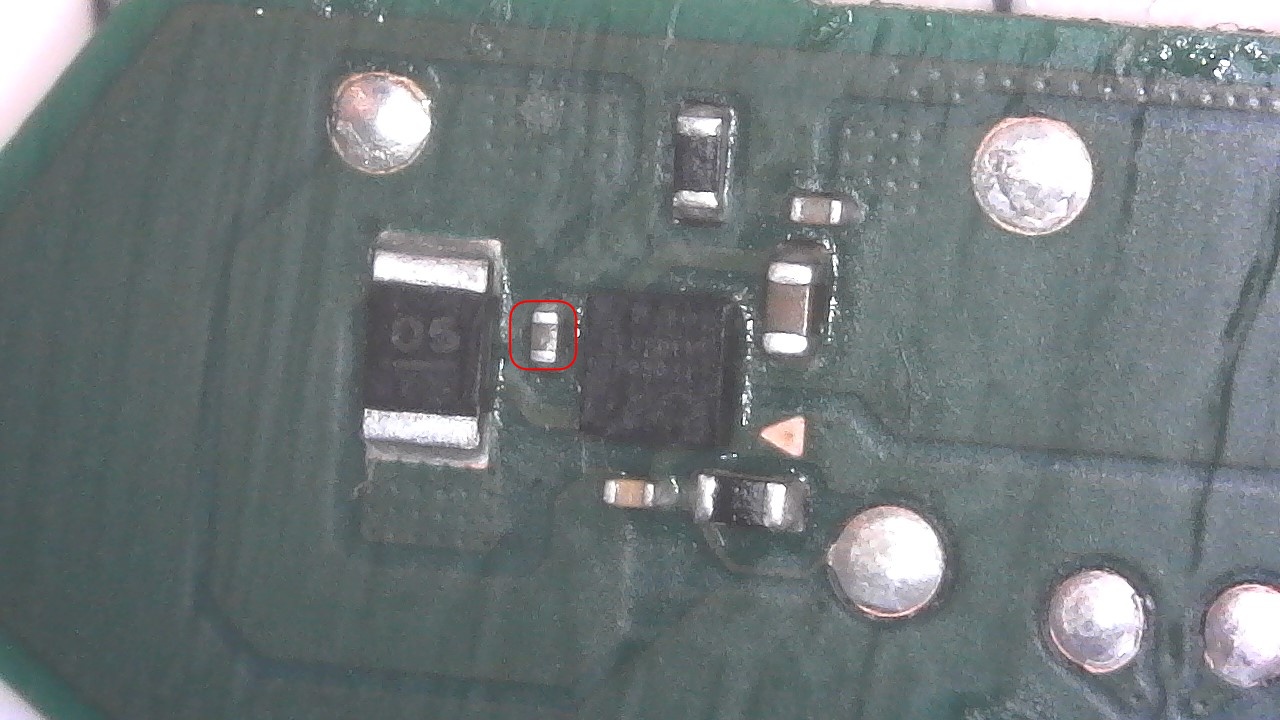
I replaced again all IC and started to take all values in diode and resistance mode. I haven’t found anything around main IC that looked completely off from Calvin’s board i collected on the forum, besides one on the back between PMIC and CPU, on a test point :
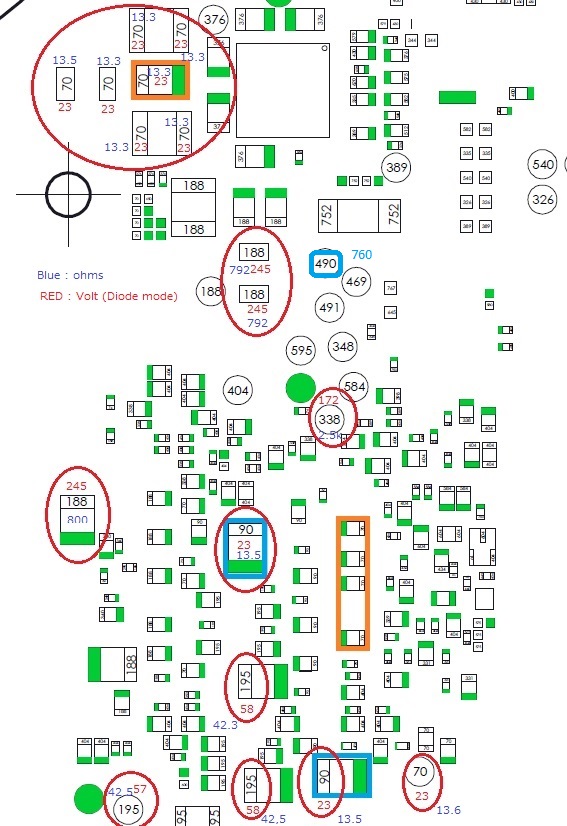
please ignore all low value that aren’t mine (i haven’t found the original without indication from Calvin), only the 760 i my off value here, all the rest that i measured on that board looks mint, perfectly aligned to diode mode from Calvin’s reading, and when doing the resistance mode for many of them (the low resistance especially), nothing crazy that i was able to found.
I am lost sorry but i don’t know where to look and i wasn’t able to find to what is related this test point. Hope you can give me a hint. As mentioned above, the CPU is also getting warm, not super hot, i would say around 40-45°C without heatsink on it.
Can you confirm, would this be the SYS rail which is shorted, or (?) if yes I would navigate around the board in resistance on this same rail : IE: at the PMIC at the two Max CPU/GPU buck regs and at the 8316 LCD IC etc and see which shorted value reperesents the lowest to get a better idea of where the culprit is… failing that, might be time to hook up a bench supply and locate the culprit at about 1V and finding it with heat output
There are the different resistance to ground i measured around main ICs
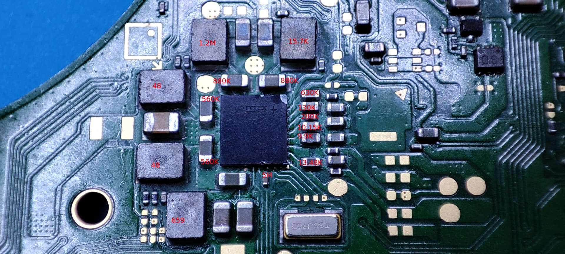
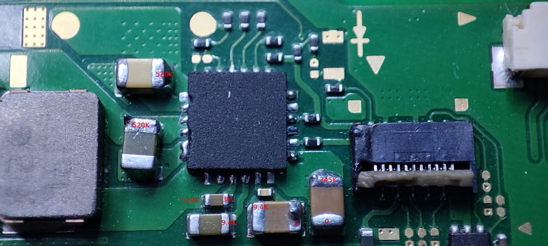
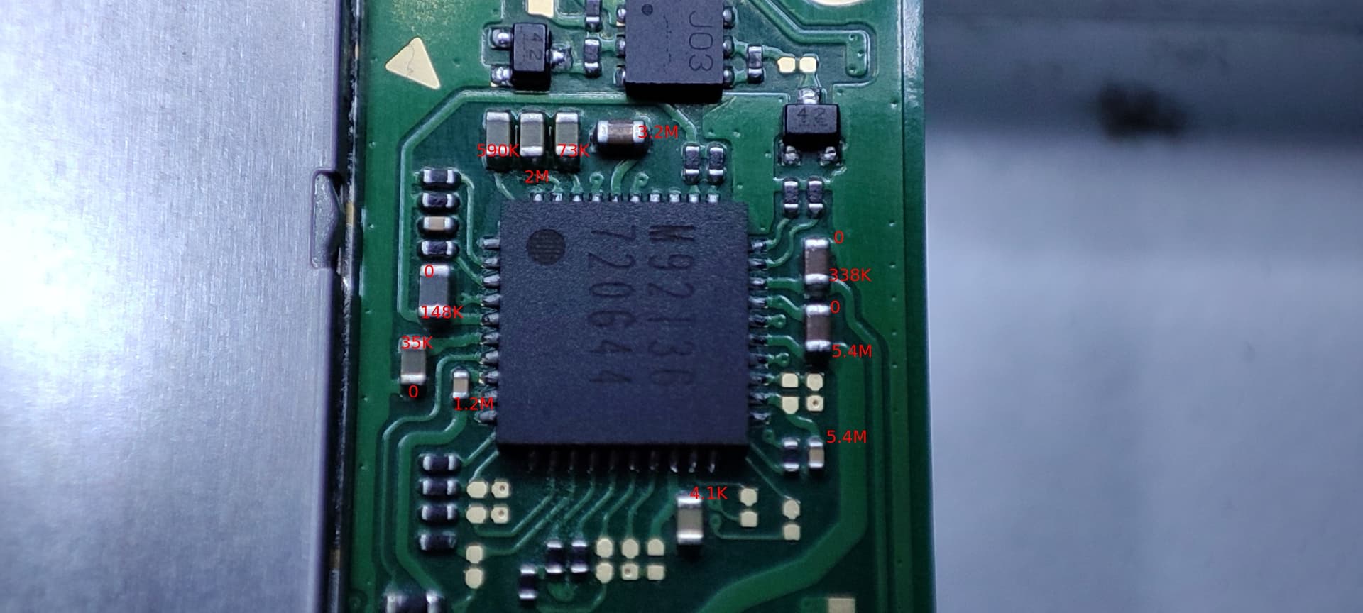
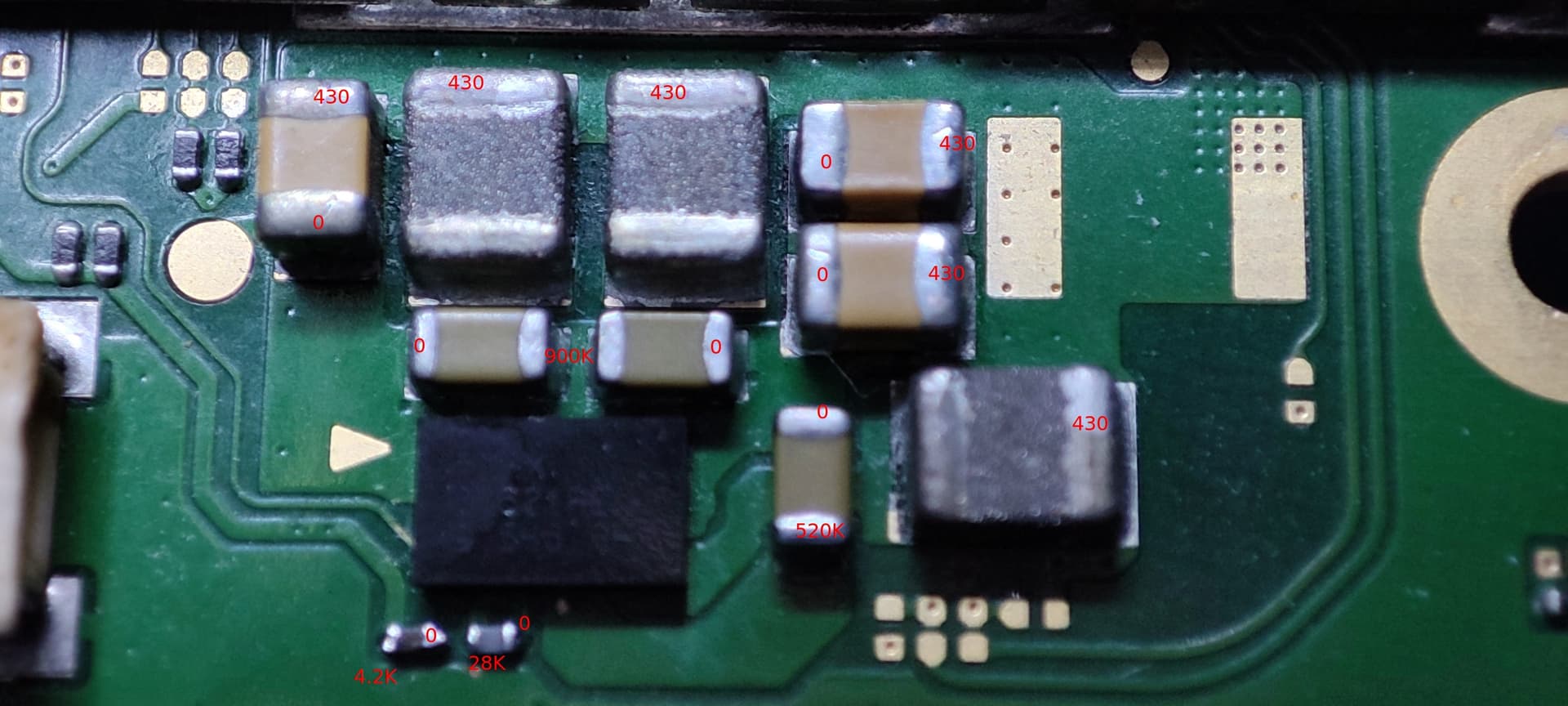
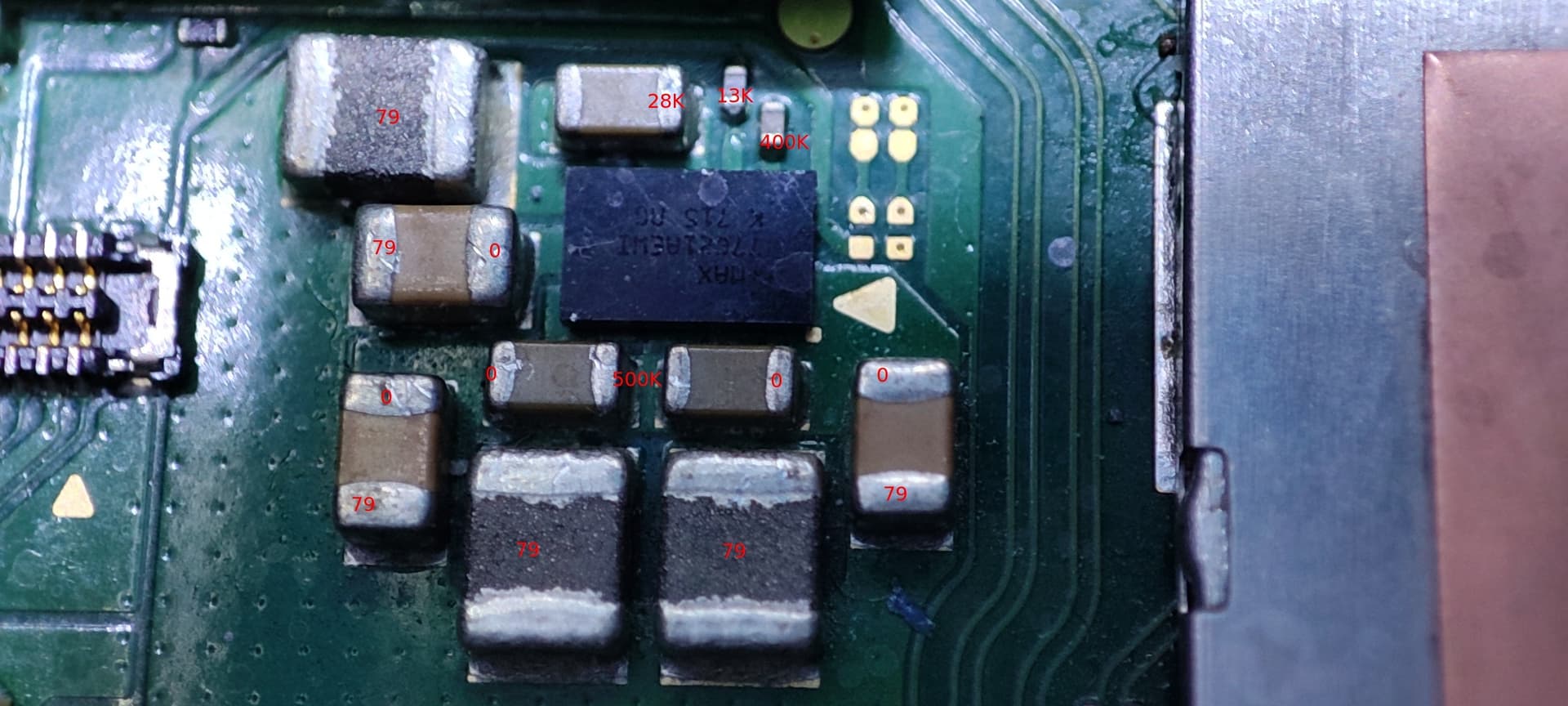
Some of the values are a bit erratic with my multimeter (UNI-T UT139), it fluctuate really a lot and i took some kind of average.
I don’t have a bench supply (yet), would be great to know what would be good to take in the future, but that’s not going to be for now (i was in another thread that you advised that one not sure if this is still relevant : KORAD KA3003D KA3005D KA3005P Adjustable Precision Digital Programmable Laboratory Switching DC Power Supply 30V 5A 60V 3A 2A|Voltage Regulators/Stabilizers| - AliExpress )
However, what i notice is a huge massacre around P13USB probably from a prior repair attempt, almost all top pins when the USB-C is down were shorted together. I fixed that since, and the issue is still the same but at least it is worth to mention i guess.
Hmm nothings jumping out at me based on your readings, but by the sounds of it resolving the USB / P13 issues has taken care of that previous short to ground.
Usually in the event of USB failures the M92 is taken out, while nothing is jumping out at me from your readings surrounding, it might be worthwhile switching that out.
PMIC is probably fine and it seems a lot of the damage to the IC is purely cosmetic and just on the poly top, but can see a few chipped corners so maybe it’s worth swapping with another IC but tbh I don’t think that’s your issue, I suppose you could prompt the console to boot and measure the voltages on the surrounding coils and ensure they’re being produced
Yeah, I mean if you can find a linear supply which matches the specs of the 5A version for a lower costs then might be worth looking at but last time I checked this was still the best linear supply for the money. You can find this model under many brand names, I think “Tenma” at Farnell has them and there is several other rebadges so opt for the cheapest you can get
I am the culprit about the PMIC marks, i was too nervous with the tweezers on it, it was the first time i was installing a BGA IC ![]()
I still need to inspect that properly, but i tried a IPA test on the board, i see 2 ICs hotter than the rest, BQ and PMIC, BQ being the faster to get warm and mostly the bottom part of it. The PMIC part that becomes hot quicker is the upper right corner, not sure if that helps. I will continue with all the drawing i see in the other posts for short on rails and try to find the culprit. I can remove the M92 as well, that’s not a concern i still have some in advance ![]()
It’s so easily done on this style of ICs as they’re so so fragile, you’ll get used to it ![]()
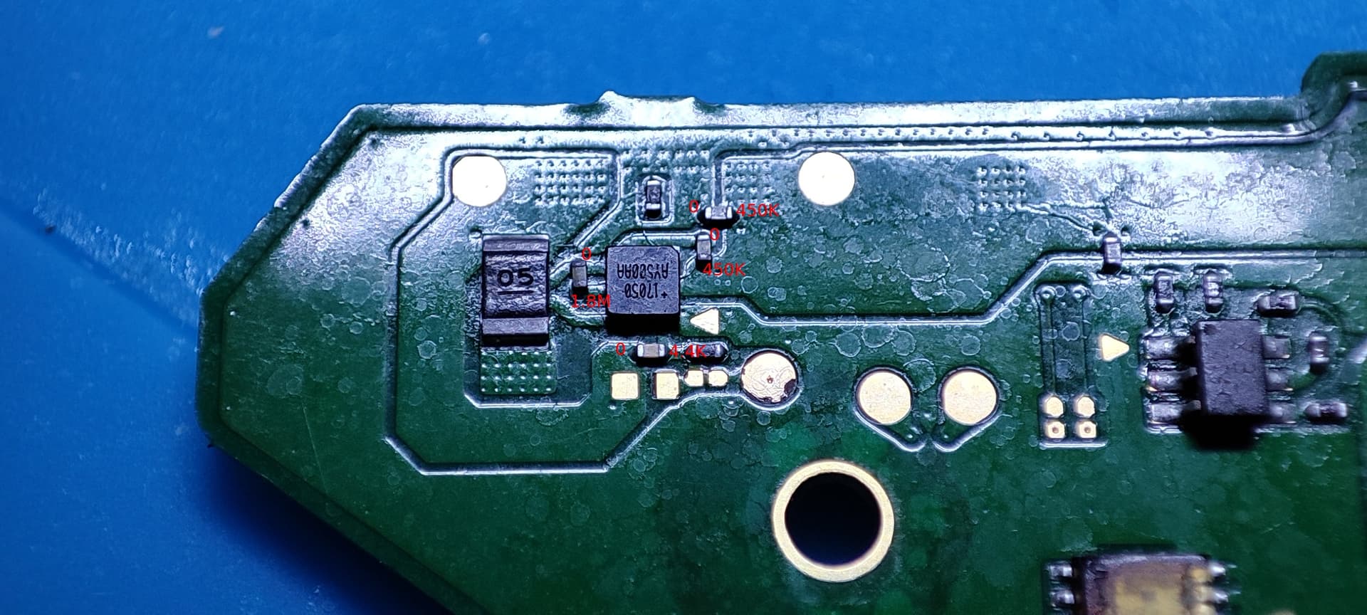
I’ll highlight a ponit in a bit nearby the PMIC where to measure the resistance to ground, I’ve found there is a common failure mode of the SoC which can be identified and measured in this area, hopefully it’s not that but worth checking
I am not 100% sure, but i have the feeling i anyway have an issue with my SYS rail as well as 1V35. Both are completely out of range, compared to Sherrifbuck’s diagram :
https://www.tronicsfixforum.com/uploads/db3735/original/2X/6/6068902a8c66f3cfc495fcd92b884eb7bbd109d4.jpeg
My SYS is somewhere around 3-4M and my 1V35 is around 100K
I think i should start with SYS, which is generated by BQ right ? What about 1V35 ? I know it goes to PMIC, but i don’t think he is the one generating it, right ?

btw here’s that point I was talking about before, if you put your black probe on ground and red on the highlighted point and let me know the reading I’ll let you know - sorry I fogot a normal reading off the top of my head but I want to say somehwere between 1.5 and 4K though I will double check
Don’t put to much weight behind this, your 1V35 rail was measuring 1.2M earlier and fluctuations down to 100K are in the realms of normal, now if you were measuring <10K on it I might start to suspect somethings wrong ![]() your better off recording these reading on another known good bood or later on a board you’ve fixed and comparing against that instead, it’s also worth keeping in mind probe polarity will atler readings significatnly, as well as ambient temps
your better off recording these reading on another known good bood or later on a board you’ve fixed and comparing against that instead, it’s also worth keeping in mind probe polarity will atler readings significatnly, as well as ambient temps
SYS being in the megs is fine, if you switch probe polarity you’ll likely see it in the kiloohms
Black probe on ground, i get 3.5K, controlled with 2 meters (UT139B and UT61E)
Okay understood.
That’s good, atleast partially rules out the SoC (though not conclusively)
Hi there,
so, i replaced again the BQ, the M92, Reflow all Max ICs and all the one at the edge on the back of the board, i reflowed EN IC above the Realtek IC, and still issue. From SherrifBuck voltage chart, i have the following :
- 3.3V = 3V
- SYS = 3.8V
- 1V35 = 0
- 1V1 =
- 5V =
- 1V8 alt. = 0
- 0V8 GPU = 0
- 1V15 =
- 0V8 CPU =
- 1V8 =
I compared with another similar board, which show bluescreen (that’s all i have from the same revision), only difference is :
- 3.3V = 3.3V
- SYS = 3.9V
- 1V35 = 1.35V
- 1V1 = 1.1V
- 5V = 0
- 1V8 alt. = 0
- 0V8 GPU = 0
- 1V15 = 1.15V
- 0V8 CPU = 0.98V
- 1V8 = 1.8V
From what i can tell about heat, most come from BQ and fuel gauge region (without being specific to the IC, but the heat is in that region), the SOC and weird, from the BGA IC at the very top of the Switch, i don’t even know the purpose of that IC, it is looking like a smaller RAM IC, labeled “GCBRG HAC STD”.
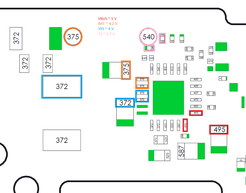
I think i have something, i just can’t tell what exactly, but if i look to this diagram :
First we agree that VBUS can either be 5 or 15V depending on the charger type right ?
But more interesting, is that my TS = 3.5V. This looks really high.
The other voltages are
VSYS = 3.8V
VBUS = 15V (or 5 if i use a 5V smartphone charger)
VBAT = 3.9V
TS = 3.5V
if that helps.
I would avoid randomly reflowing ICs without proper evidence to do so, all you’ll achieve is stressing the IC’s or the board out which may lead to unintentional secondary issues which can make diagnostics later on more difficult ![]()
None of the rials from the main PMIC are being generated, so either it’s a fault with the PMIC itself or the console is not being prompted to boot which implies USB or M92 isses (or the surrounding support components) I would frst attach the power/vol flex cable (or short the pins with a tweezer for pwr button) and press the power button and then check to see if anyof the rails are then present, if not I’d check the two ESD diodes for the USB and check they aren’t shorted to ground, check the fuse near the USB isn’t open, check M92 is soldered properly and check there is no issues on the surrounding components (open resistor for example)
icbw but think it’s related to game carts … maybe authentication of some sort… I forget, this rarely ever fails so unless you can see signs of prior rework or corrosion or unless you measure a short on the nearby bypass caps (though I doubt you will based on your previous measurments elswhere) then don’t think this is your issue
I’ll look into this, can’t remember tbh - what does it measure on your bsod board?
Ok got it, i won’t do it anymore, i promise ![]()
ESD showing wrong value (no 0L in diode mode for the both edge corner opposite to ground), i removed them.
USB already tested with a test board, looks mint, no short between the leg and continuity is perfect.
Fuse is ok, M92 is perfectly soldered, no bad joints, no shorts, all resistor surrounding showing a value (in between 10 and 100K i think), no shorts on the caps.
Replaced PMIC, got additional voltages, now the list is as following :
3.3V = 3.3V
SYS = 3.9V
1V35 = 1.35V
1V1 = 1.1V
5V = 0
1V8 alt. = 0
0V8 GPU = 0
1V15 = 1.15V
0V8 CPU = 0.95V
1V8 = 1.8V
So pretty much in line with my BSOD board, but nothing on the screen even if being prompted to boot.
Around BQ i have the same as before, and the BSOD board is also having a TS of 3.5V.
And suddenly it booted, without anything additional made to the previous post 
i will monitor this, make a good ultrasonic bath because flux is everywhere with all the ICs reworked, and that is one fixed thanks for the help again
Cool ![]()
Based on your previous voltage measurments when it wasn’t booting, you were getting CPU voltage present, so usually you would see the first Nintendo logo, so perhaps you have an issue with the backlight connector or ribbon (somtimes the backlight ribbon is prone to corrosion or pad damage on the flex) or LCD ribbon or connector issues
That all being said, you were missing GPU voltage which is a bit disconcerting, you would expect that being present after a few seconds after prompting to boot (though if I remember right this rail drops when the console is in sleep/standby so maybe that’s why it was missing in your previous measurments)
Glad to hear you’ve got it up and running and hopefully after a good scrub it will continue to do so ![]()
1 Like