I changed the MAX77620 chip out because I am stuck in slow charge mode and I (thought) I had found some shorts near it. Since I’ve already put in a new MAX17050 twice I figured my problem must be somewhere else and that looked like the problem.
Suffice to say after changing the chip I have lost my 1.8V and 3.3V on the testing points seen in the photo. I definitely had them before the exchange. Should I change it out with a new chip or should I suspect another culprit is to blame?
This IC is the main PMIC, it has no relation to charge management so was never your issue.
Probably not shorts, measure resistance instead next time
Destroy that photo, it’s useless , instead if you want to check that the PMIC is producing your primary rails then check on the inductors surrounding it instead.
If your not getting your pimary rails since swapping the chip following prompting the console to boot, then it indicates your install is bad… can you talk me through your reball process? same for the fuel gauge, can you let me know your reball process here too?
Hopefully this hasn’t caused permanent damage to the SoC etc
Well, as embarrassing as this is at least I learned a valuable lesson.
I haven’t reballed anything, the replacement chips I ordered came preballed.
When I originally got the switch it was charging at 0.09. I replaced the m92 and it began charging at 0.47 with nothing in the screen. I’ve seen this quite a few times and every other time the 17050 was the issue so after replacing it and seeing that it still wasn’t working I was kind of in the dark as to what I should do next.
For my knowledge, why is it bad to use that photo? Are these points inconsistent or possibly just not useful as a troubleshooting tool?
I see, so providing the replacement chips were good, and you properly wicked the pads prior on the board and didn’t skew or misalign any of the balls during reflow then there’s no reason they shouldn’t work. I’d just take the oppurtunity to look at these ICs in close detail though and ensure neither have any chips or cracks to their packages, also edge on. I’d aslo check that your PMIC revision number is correct, if I remember right there is an “A” and an “H” revision, one of them is typically on Maiko boards… I have no idea if it makes a difference or not and if the two are interchangeable as I’ve never swapped between the two.
If you were prompting the console to boot using the USB cable and if you have M92 related issues (due to a bad install for example and in turn a resulting failed M92 IC) then you won’t see the primary voltages produced by the Max PMIC (on the surrounding inductors) and you should instead try prompting the console to boot by either attaching the power button flex to the board and hitting the button or by jumping P+ to ground on the connector with tweezers and seeing if you then get your primary rails produced by the Max PMIC.
All of the above, additionally it provides no infro as to what the rails relate to or what power state the console is in, for example are these recorded on a board which is promtped to boot or merely has the battery connected, is the USB connected? are these standby voltages? etc it’s providing rails which have no context to the IC which generates them… just a random mishmash, don’t recall if it’s this image or not but pretty sure it’s the same “ConsoleX” source…voltages (using the same colour) of completely different/independent signals and rails which can lead people to extreme confusion.
I will have to check the revision number. I believe I remember reading that the revision number does not matter in this case but I could be wrong.
It actually does have a small chip on one of its edges. I am uncertain if there may be bridging under the chip at the moment. When installing it, the solder got to it’s wetting point while slightly off center then with a very slight nudge it pulled itself into position. I was a bit anxious about this to start and when I was no longer getting voltages I assumed I messed up the install.
I will try to initiate a boot sequence tonight and see if anything changes on the power rails.
Something else I should mention, while the charging is indeed stuck at 0.47, sometimes when I try to initialize boot, the Amos will drop to 0.25(ish) for a brief moment then back to 0.47. I am unsure if this is significant or not. I am new to electronics repair and am taking notes to make myself a troubleshooting guide for issues I have come across.
Thank you for your replies. I see your name come up often and it is people like you that keep these kinds of forums alive!
Follow up, I have changed the max77620 again…but back to the original chip…and my power rails all seem to have been restored. All identical readings to before. I believe the replacement chips I ordered are either bad themselves or just poorly balled and I can promise I won’t be ordering from them again (and I’ll be looking for a refund). Either way it feels good to have at least been able to put the original chip back in place and get those circuits back.
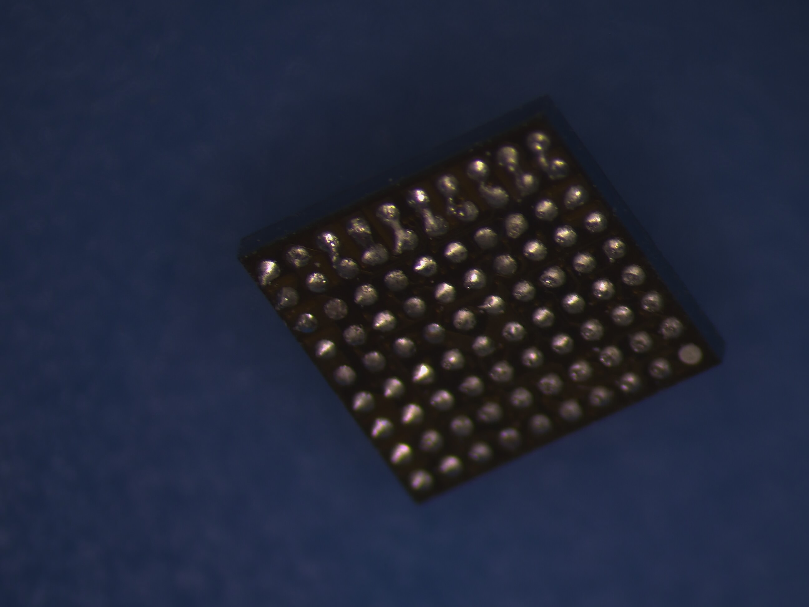
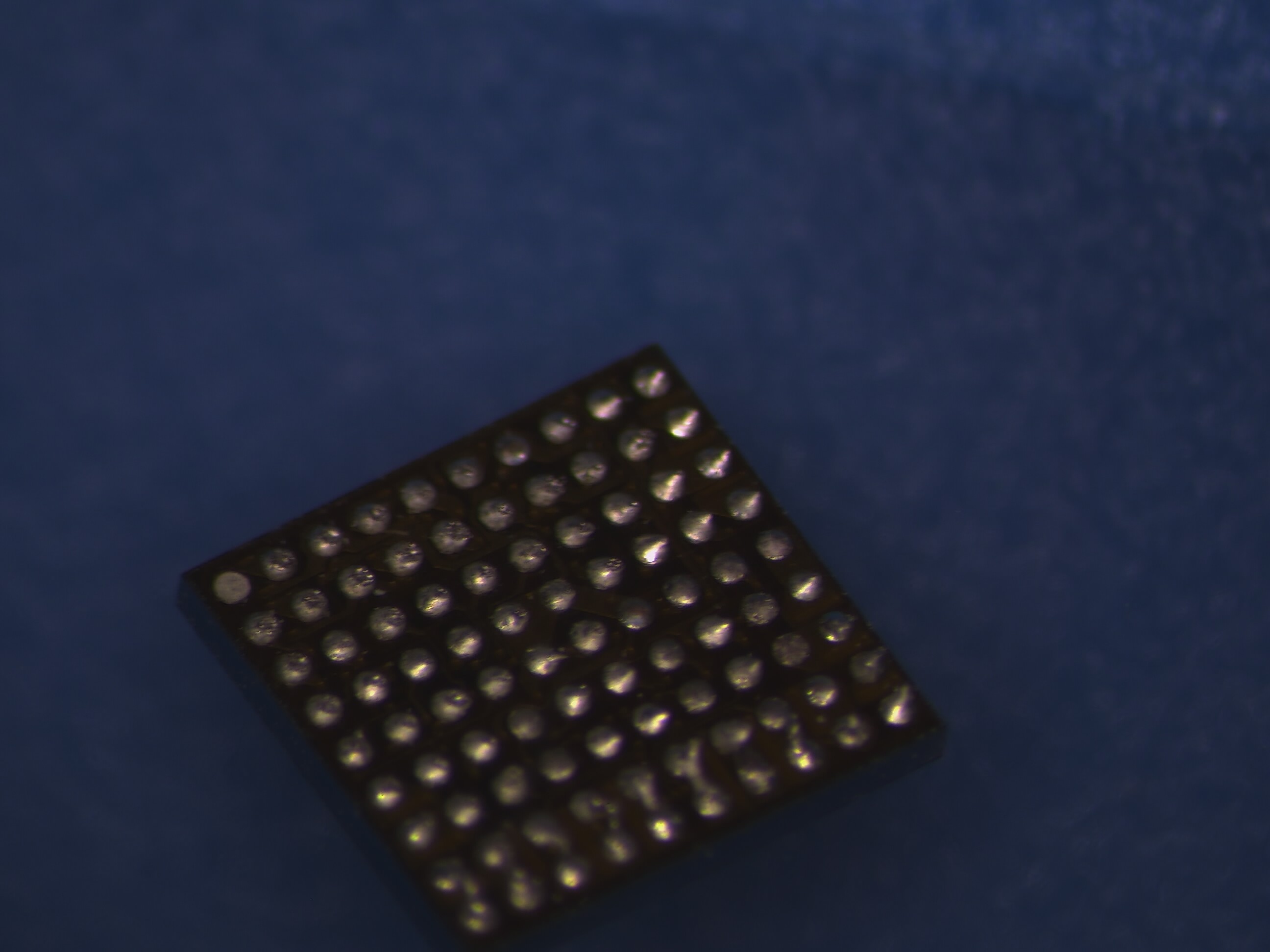
If those images are of another “preballed” IC… then that’s shocking… looks like they just ran over it with an iron, badly. I mean if the listing doesn’t explicitly state that the IC is preballed then that might be there out, pretty sure this chip is only availiable from donors so perhaps they’re selling with the expectation that your supposed to reball them
Just bringing your other topic back over here so it’s easier to follow instead of replying in three different threads
I don’t recall seeing that error in Hekate before, but accoriding to the developer over on Github, it’s as a result of corruption on the SD card, I would format the card, redownload the Hekate files and re-place on the SD card. I’d also take the oppurtunity to inspect the SD card pins on both the board connector and the SD flex connector and ensure none of the pins are bent or that any of the joints are loose.
From your images in Hekate, notice how it’s reporting the temparature as 00.0 C, this would be pointing to an issue with your TMP IC (next to the backlight connector) either as a result of the chip being bad, or because it’s not getting it’s required voltages or signal, it’s also entirely possible a more serious issue is causing this
Sorry to have ever multiple threads, I thought it was the better option since the source topic was different.
The listing has these chips as “new” and the photos of the chip clearly show a very well preballed chip but I don’t remember if it says it explicitly.
I think I am ready to move on from this board and use it as a donor board. I appreciate all of your input and either way over learned quite a bit. I have a lot arriving today of switch lites I will be working on and maybe if all goes well I will return to this board in the future, but as of right now this one has exhausted me, lol.
I put the ic on my silicon mat, in the focus of my camera and place the stencil on the ic. I hold the stencil with two fingers and apply solder paste with the other hand. After applying enough solderpaste and cleaning the surface of the stencil, I take my tweezers and hold the stencil down, while applying hot air.
Hi am new here. Thanks for the information so far.
Pls I don’t have 5v on the switch board am currently working on. Other voltages are present. Pls which ic is responsible for 5v. And it’s not shot to ground. Thanks