Coil Whine upon Booting and when Waking up the handheld

My Switch Lite whines when it’s booting, but that only happens during the Nintendo logo screen.
Right after that, screen goes to black and then when the Switch logo appears, the whine is gone.
After entering sleep state, if I attempt to wake up the handheld soon after that, (5 to 8 minutes after sleep mode has started), it wakes up just fine. If I leave it sleeping for longer than 10 minutes, I can hear coil whine upon waking it up and this buzz goes on and on. Curiously, after coil whine has started, if I press the power button, making the Switch Lite go to sleep, and then wake it up right after that, the whine is gone. Oh and this is important: Every time the Switch Lite coil whines, screen brightness goes all the way up to 100% and the slider won’t set it down, it won’t work.
I attempted to listen to it very carefully, and it seems it leads to this area:
my_photo-105 my_photo-107
Now, it could have to do with something from the other side of the board but I think it sounds way louder from the side I took the picture.

What could be my issue?
Please help me out. Thanks in advance.

Upon further testing, I’ve come to the conclusion that whenever “coil whine” happens, it is not to tell me that a component is working - rather, it’s from the potentiometer saying something is wrong with it.
That’s why screen brightness goes all the way up to 100% and will be stuck at that. Trying to lower it down doesn’t work, so the potentiometer doesn’t work. That’s what happens when coil whine takes place.
However, pressing the power button to enter sleep mode and then pressing it again right away and everything works, screen brightness goes back to where it was.
So why is the potentiometer behaving like that? Could it be because another component is providing more current than it can handle? Could it be those caps on the daughterboard, next to the backlight? I need some answers :S

IC marked U79 appears to have been reballed, and it may just be the lighting but appears to have a knick taken out of it.

If excessive heat was used in this area then the coil insulation may have been damaged altering the inducatance values.

If it were me, I’d start by replacing the IC and Inductor and see if anything changes.

I know this may sound stupid, but I’ve got to ask.
According to your statement, the chip labeled U79 has some solder sticking out. I would try and fix that but I have no idea how to desolder it from the board because its casing doesn’t give any indication where to begin with. Could it be resoldered or has it gotten to a point only a new one would help me fix this issue?
As for the inductor, I thought that chip next to U79 was the potentiometer for screen brightness control and the inductor was on the other side of the board (2R2839F component). So could you please confirm that that component is indeed (another) inductor?

Finally, I was told coil whine typically comes from some power converter. Is that why you mentioned if it were you, you’d start by replacing the MAX77620HEWJ IC component? Or were you referring to U79? Considering I’m unable to set the screen brightness up or down (for it will always stay at 100%) during coil whine, should I also consider MAX77620HEWJ as the culprit too?

I’ve noted what all the parts are in this area for you to avoid confusion :slight_smile:
Parts labeled

No such thing as stupid questions, were all learning.

It depends on the fault (if it was poorly reballed for example) and if the die of the IC doesn’t have any chips or cracks and looks fine then it’s possible you could reball and re-use it.

It’s not a potentiometer, the Backlight driver IC is in a way acting as a digital potentiometer…putting it loosely.

From the datashet,

The TPS61162A and TPS61163A support both the PWM dimming interface and one-wire digital EasyScale™ dimming interface

Indeed, the Backlight IC is a converter, and the whine will likely come by way of the inductor next to it.

I say this incase people misunderstand what i say and proceed with repairs outside there norms, I don’t want anyone to blame me if something goes wrong :wink:
It’s also entirely possible thatwhat i mentioned above isn’t the cause of this fault, Do you have a oscilloscope or logic analyzer by any chance?

No this IC is unrelated in this context.

Yeah.

No.

@Severence thank you for pointing out those components, I really appreciate that.
I wish I had read that answer of yours before trying to find out the issue and/or investigating even further myself. I went from having a working Switch Lite (Video + Audio + coil whine) to a semi-working Switch Lite and then a fully non-working handheld.
Here’s the reason: as nobody on the web has run into the same issue as I do, I then decided to investigate the ZIF Connector on the daughterboard. The reason I went for that component is because having it soldered onto the daughterboard was my last job on this handheld, before the coil whine issue came to happen. My guess was that I would be able to find something or some undesired joint that could be causing this issue. I found nothing. All of the connector’s legs are soldered onto the board, it was a great job. Each of the three pins for the backlight lead to its own via, no bridges. No caps knocked off of the board. It should just work, but without the coil.

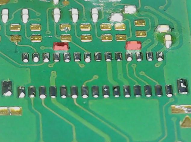
So I decided to connect the interconnect cable again, this is where things started going south for me. Daughterboard connected just fine, but when trying to connect to the main board’s connector, I found some resistance to fill it in all the way, no matter how many times I pushed it in. Later I discovered that the edge of the cable somehow grabbed one of the internal pins. The more I pushed the cable in, the more I was actually pushing the internal connector up. Had it been one of the pins right in the middle, it’d be visible. But no, it had to be the very first pin from the left. Never would I be able to use the same connector again, which means I was F-ed because I would have to solder another connector, but this time to the MAIN board. Sound was still working tho. But during preparation of the pads for the next connector, I ended up knocking off these components in red (a 150 Ohm resistor on the left and a 0201 MLCC capable of handling at least 17V for the backlight, according to MyMateVince):
NSLissue2front

After another connector was soldered onto the board, I decided to check each IC I know could prevent the Switch Lite from powering on.
On the back of the board, next to the USB-C port, there’s this diode:


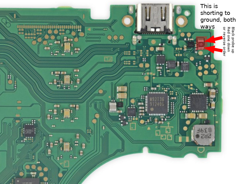
And it’s shorting. It beeps when I touch each end with the testing probes, no matter which one is on each side. Is that supposed to happen? Does it happen with yours too?

Still on the back, there’s the MAX77620HEWJ Power Management IC (According to Ifixit), it’s surrounded by caps. The bigger ones on the right side (highlighted in red) are shorting to ground:
NSLissue2back
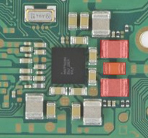
Again, does that happen to yours?

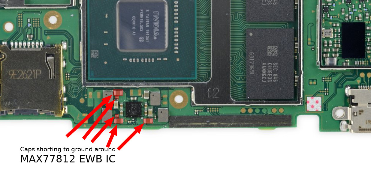
Finally on the front side, yet another IC with problems. At least that’s what the caps around MAX77812 EWB tell me (highlighted in red):

I guess anyone would throw the white towel at this point and call this a donor board.
But I can’t help but feel like I’m still learning with this. I’ve spent over 12 hours with this Switch Lite out of my spare time and I’m not ready to give up on it just yet.
I want to fix it. Back with video, audio and no coil whine.
Oh and speaking of it, I was told that if I remove that coil you pointed out in your previous post and bridge its spot with solder, that would fix my issue. Could you please confirm? Would that be a solution? No, I’m not lazy, it’s just complicated to look for something that has no label on it, as I have no spare components to try, let alone spare devices to tear down and rip it off to use on my Switch Lite.

So if anyone who owns a Switch Lite or knows how those IC’s I mentioned work could be able to let me know whether those caps are supposed to beep both ways or do they indicate that those IC’s indeed need to be replaced?

I’m sorry about the long post.

Hey, no worries.

So I’ve highlighted a few of the components surrounding the main PMIC
Inductor highlighted
The parts marked in blue are inductors if you look closely at the coating it almost looks like glitter this is the ferrite, these are all on the “outputs” of various rails including 1V8PDR, 1V35, 1V1 etc which serve various purposes, EMMC, SoC, Ram etc.

The reason I don’t suspect the main PMIC is at fault is because without these primary/critical rails present, the console wouldnt boot, or should i say it won’t boot for long if a fault was present here.

the part marked in red is a capacitor serving as bypass for one of these rails. Can you provide the resistance accross it?

I don’t have a Lite board here to verify but the circuitry is largely the same albeit with a slightly different layout compared to an original switch board or Mariko, but as far as i know the IC next to it is the fuel gauge and the component you’ve highlighted in the image is a current sense resistor, it is normal for it to test short to ground as it’s serving to measure the current through the battery negative.

It’s completely reasonable to suspect the connector here or the opposing one on the mainboard, and I think you did the right thing investigating it. A fault here could well have caused the symptoms you were seeing either as a result of poor prior soldering or because of scorching inside the connector itself.

It’s likely normal, the rails which these caps are serving as bypass are low impedance lines. Can you measure the resistance accross these caps?

The IC here is a dualed up package of what came before and provides power for the CPU & GPU.

Not at all, and as you say it’s a good learning exercise.

It’s not a good idea. Check out the backlight driver IC datasheet, it might well explain for you what the purpose of this inductor is (if it doesn’t let me know and I’ll go into further detail regarding this for you)

The console still boots right, it just has all the issues relating to backlight and coil whine etc?

If yes then I’m still leaning toward the backlight driver IC as the culprit. If you want me to check the Inductor value for you than I can do, it’s also highly likely it’s the same as the one detailed in the application circuit detailed in the IC datasheet.

This handheld no longer boots. Testing the board only, no battery connected to it. Multimeter set to 2k Ohms. Black probe on ground, red on the cap you highlighted in red, and it reads 0.10 Ohm. If you could provide me a description for that coil whine, that’d be helpful.

OK.

So as you can tell, it’s a mess right now. My mind is set to defining which IC or region of the board I can find the most issues at, so that I can focus on it first. So lets just pretend MAX77812 has more issues than the Power management IC on the back (which does have its issues as well, but as a side effect of the previous chip’s) – I want to tackle MAX77812 because in theory I believe by replacing it, maybe it could in turn make the PMIC work as expected.

@Severence out of curiosity, what would you do? I’ve yet to define which chip I should purchase. Also, any hints for a website that sells Switch Lite parts in the US?

I haven’t got my documentation in front of me and am not as familiar with the arrangement of the components on Lites/Marikos, but given your readings (which are indeed not good) it’s likely you have a short on the SYS voltage rail.

You can find this on the large inductor next to the BQ IC, can you put one probe on ground and the other on either side of the inductor (doesn’t matter which side) and let me know the reading?

Coil whine is actually normal and is a side effect of the way tranformers, inductors etc work they’re simply resonating or vibrating and emitting that frequency as an audible sounds, how high pitched or low pitched it is depends on the frequency. Manufacturers of these components will pot or coat the enamled wire within the ferrite in order to minimize this.

In your case the fault (which we suspect was originally a bridge/short somewhere) was likely altering this frequency making the whine more audible than it otherwise should be, it’s also possible there was some negative side effects if the backlight driver IC was being pulled low on it’s VIN, I haven’t double checked this but it’s likely being supplied it’s voltage input from the SYS rail.

Red probe on ground and black one on either side of the inductor next to the BQ chip gives me .086 Ohm (again, multimeter set to 2k).

Can you remove this inductor and let me know which side the short remains on.

btw I don’t know if I answered you question as intended above, if you meant more generally the purpose of an inductor then if you search on youtibe for afrotechmods he has very likely covered the purpose of an inductor before and will for sure explain it better than i could :slight_smile:

I will let you know once we start narrowing down the primary fault. Also some IC’s can’t be purchase and have to be salvaged from donors and reballed with advanced equipment.

I’m in the UK. but Mouser, digikey, Element14 are all safe bets

Great discussion here. The Switch Lite can be a right pain, particularly with this flex linking the two boards. It’s quite a rubbish design as they run 17v backlight driver lines right alongside 1v7 lines used for the buttons, so all hell can break loose when those connectors start to break down or you don’t press it home fully, or forget to power down when you fiddle with it (Yep - done that). The backlight driver IC runs from VSys and can push out quite a current without cutting out, so there is a possibility you have damaged the backlight IC which is now causing your short from VSys to ground.

Logic says the failure is connected to the connector issues were having and the backlight driver IC is the only VSys item in the vicinity. Might be worth pulling it and see whether the short goes.

Good luck!
Sheriff

Hey @SheriffBuck, thanks for stopping by and sharing some knowledge.
@Severence I’m so sorry for leaving the conversation like that for a few days, my work got in the way and we spent over three days fighting against a ransomware for my company. That’s just the beginning of the story, but since that is unrelated, I heard your last comment and you suggested to desolder the coil which is next to the USB-C port, Sheriff said to do the “U79” IC which is right next to the coil whine - that is, when my Switch was booting.
Right now, I just want to let you guys know that, without desoldering anything, I get no video and my ampmeter says the Switch Lite is outputting 0.41A.
First, @SheriffBuck 's suggestion. I desoldered the “U79” IC next to the screen connector on the main board. It didn’t change anything as the readings I posted on my previous post were pretty much the same. Ampmeter says the Switch Lite still outputs 0.41A @4.99V.
Next, @Severence 's. I didn’t solder the IC back onto the board - instead I desoldered the inductor and while I was hopeful there was going to be a short on its pad, with red probe on ground and black one on the pads, it turns out it isn’t shorting.

I need more suggestions :frowning:

EDIT: Oh and a side effect from removing the inductor, the Switch Lite will now output 0A. It’s pretty much dead for now.

Hey.

With the inductor removed, you will get 0A. No need to panic. Can you specifically measure and provide readings from each of the two coil pads. What @Severence is trying to determine is whether the fault is upstream or downstream of the inductor.

Once we establish those readings, I can suggest next steps. I’ve got a few boards here that may help with readings.

Sheriff

Hey @SheriffBuck, I wasn’t sure if you wanted resistance reading or something else, so I’ll provide both (board positioning: USB-C port up):
[Diode result - red probe on ground]: left spot: 376 / right spot: 085 (beeps)

[20k Resistance result - black probe on ground]: left spot: 1 / right spot: 0.71
-> red probe on ground: left spot: varies, then gets to and stays at 1 / right spot: 0.55

While we’re at it, would you happen to know the value of this cap (yellow arrow)? I think it’s a 0201 one, but I don’t know its working voltage and capacitance.
As for the blue arrow, I don’t think there’s a component there, just a spot. But it could also be another resistor. Could you please have a look at one of your Switch Lite boards and let me know?

Can you highlight these readings in an image just so I can see which side is which?

It would seem based on those readings though that you potentially have more than one fault on this board, typically (but not always) SYS shorts are caused by a bad BQ IC, it might be worthwhile pulling that IC and see if the short on one side of the inductor pads clears.

Oh dear, well let me know if I can help in any way, In the past I’ve helped a few people where there data was encrypted by some ransomware group and I managed to resolve this.