Hi guys,
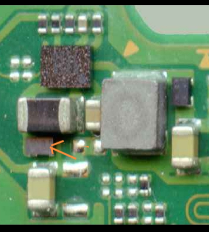
I messed when changing that tiny Max17050 and some tiny 0201 capacitors and resistors flew away.
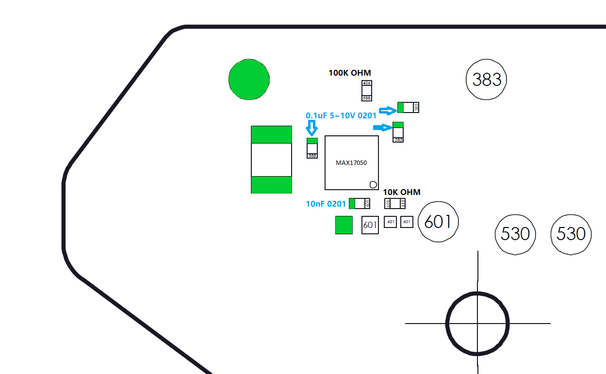
I didn’t find any image about values around there, but found a nice picture online with pads and continuity (sorry, I don’t know exactly from where, could even be from here, but when I come across one of those I just save them in a dedicated folder). Using this with the datasheet (https:// datasheets. maximintegrated .com/en/ds/MAX17047-MAX17050.pdf page 12) I was able to “map” which is which, but it’s not exactly what it’s supposed to be when compared to values I found on another switch, so I’m in doubt.
First the big resistor that link CSP to CSN should be 10mohm but I tested continuity (0.02ohm). Second the optional on alert that is supposed to be 200kohm, the original picture says it’s 100kohm but I tested a fluctuating value around 15kohm.
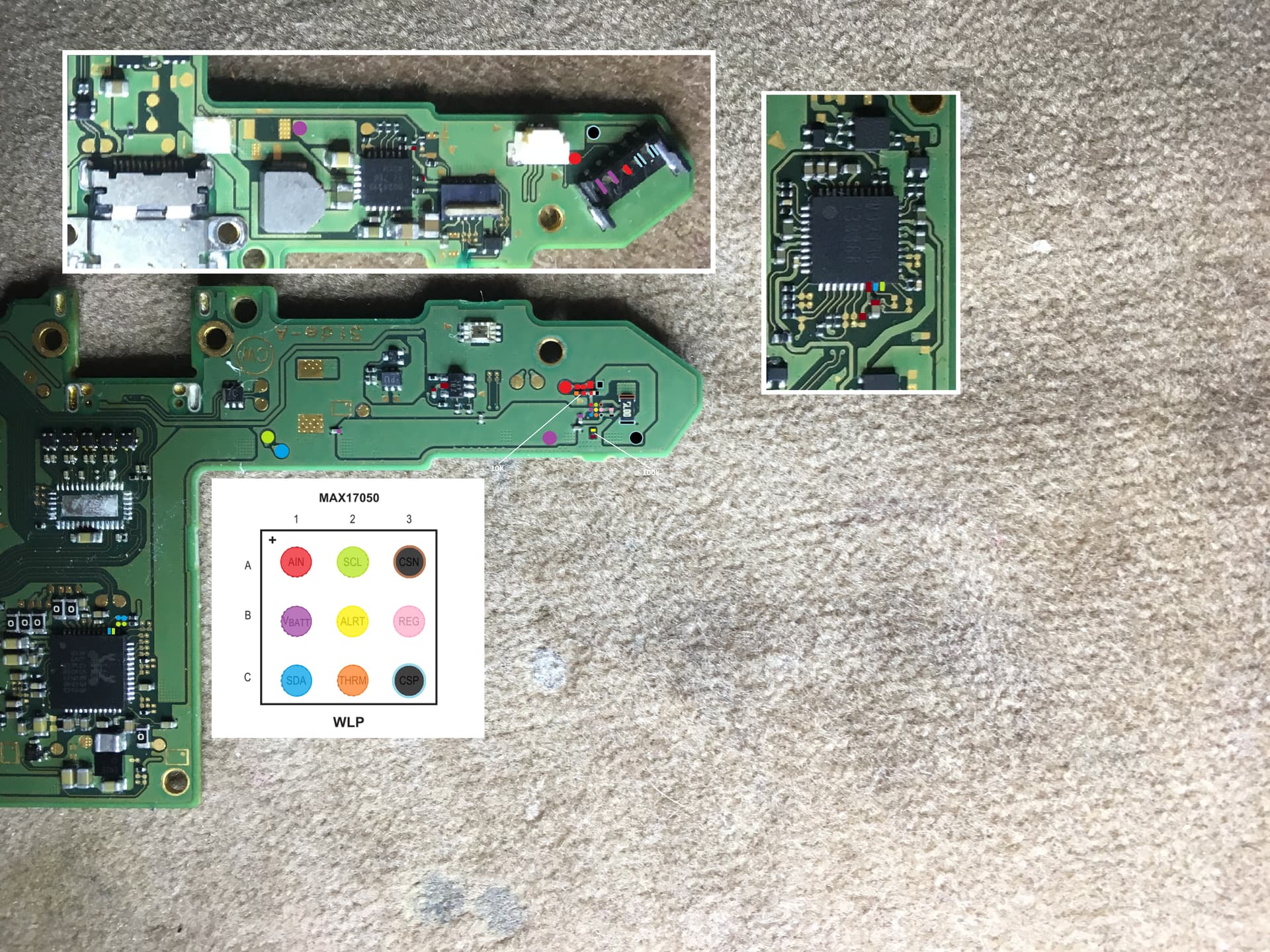
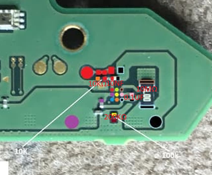
Also there’s one cap I didn’t write anything on, the purple one, because if you look at it, there are actually 4 of them on the same line, this is from vbatt and is supposed to be 0.1uf (so is it 4x0.1uf or 4x25nf?).
Anyone knows the correct values?