Hi!
The patient is BDM-030 with three blinks of death. There is evidence of one analog sensor being replaced, since its casing is black, not orange, and there’s remnants of a bad solder job on the back side, as if I myself did it. The caps near the analogs are intact, not shorted either, there are no shorts to be found in any obvious other spot, like across the + and - of the analogs, or near the charge IC. The device does not charge, however, and even though the battery is around 3,6v, that voltage is there at the entry of the component in question. On its output it drops to 1,33v though. When I check for continuity, there is none, both ways. I’d assume there is a fuse and a diode in this area, but I can’t be sure which is which. Any help or links to relevant schematics would be appreciated. Thanks!
Hello, no diode or fuse here. Normally, when the controller flashes orange 3 times, it means the battery is not connected. If you plug it in normally, the controller works.
But the thing is the controller blinks with the battery connected, and there is battery voltage on the output of the Dialog chip. When connected to USB, the battery is not charging, and the dialog’s output voltage is at most around 4V, where it should be a nice clean 5V from what I gather.
Sorry I got confused. It’s when the controller flashes orange twice that the battery is missing. I’ve still had the controller flash 3 times several times and often it’s a problem with the connection of the ribbon cables for the r1 r2 l1 l2 keys and the vibrators. To find out, just unplug them and see if the controller works. That said, I have one that worked normally for which I changed the sticks for hall effects, and I ended up with the 3 times orange. So I put the analog ones back but the same thing. From what I’ve read, it would be a CC. I haven’t found one. So I’m looking for where it could come from by removing and replacing the different chips one by one. For the moment nothing, I still have the SIE to do. I’ll keep you informed as soon as I have news.
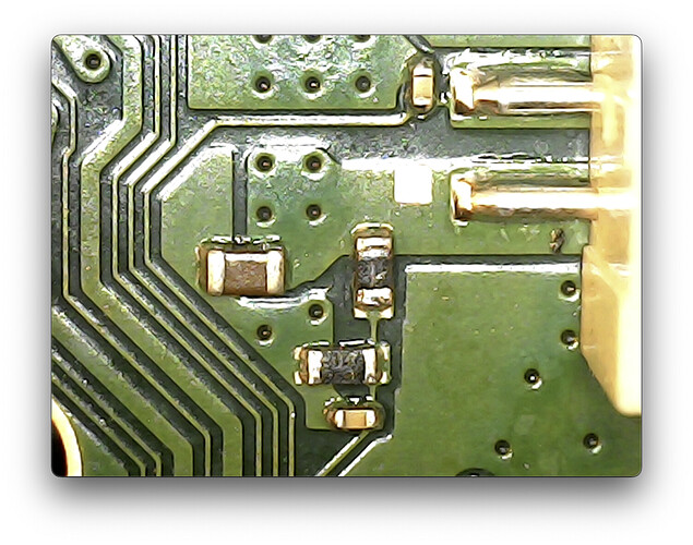
I returned to the controller, because it was taking up the drawer space. If finally works! One thing I would constantly ignore was a missing component in line with the white battery wire, next to a series of capacitors, among which one closest to it was lightly bumped, although still connected to its pads.
Marked green in the photo.
Seems whoever was attempting to replace the right analog hit that component and lost it, and slightly moved the capacitor next to it.
From the looks of it, the said component pulls down the thermistor output from the battery to ground, but I can’t be sure.
First I shorted its pads, connected the controller to USB, and it blinked twice, meaning a missing battery. Interesting! So I connected one and the thing started charging.
As a semi-permanent solution I put a 10k resistor there, but I still need to identify the actual component that is supposed to sit there. So if anybody has a BDM-030 board at hand please check what this thing is if possible.
I ignored the fact that the component was missing I guess because the controller would always blink three times no matter if the battery was connected or not. Once this connection was fixed it started behaving the way I made out from my research as correct, i.e. two blinks == no battery.
For now I installed some TMR analogs, and replaceable analog caps, and it’s starting to look pretty decent!
what is the resistance value of that resistor?
For now I put a 10k resistor there just to be safe. Did some research and couldn’t find any suggestions what value should land there, but given there were discussions on how to make the controller start without any battery connected, by either shorting the white to GND or putting a 10k resistor between them, I figured this value should be fine for the time being.
I asked ChatGPT to do some additional research and it came to the conclusion it’s 10k too, citing industry standards of using NTC 10k thermistors.
I looked for a simple example of reading the temperature from such a thermistor using, say, Arduino, and in the first I found, the thermistor is connected from the other side to 5V, and its output voltage is halved by using another 10k resistor pulling thermistor output to ground, so the ADC can safely read its output.
It just so happens I recently got a drifting BDM-030 Dualsense to put TMR sticks into, so I’ll check the resistance while I’m in there.
One other thing, with absolutely nothing connected except for the battery, BDM-030 starts up. That doesn’t seem to be the case for BDM-020, which I recently bought with a destroyed trigger fpc connector on the assembly side. This one welcomes the user with three flashes if none of the triggers are connected. Both had very old firmware installed though, so this behavior might be different in later versions, perhaps the later ones to more sanity checks before the controller starts up and connects. Now they’re both on Jun 2024 revision, I’ll check how they behave next time I have them on my bench.
I took off and measured the little buddy for science, and it read around 7.5kohms while still scorching hot, which is the same value when it’s soldered on its pads properly. So I guess 7.5k it is. Weird,
Oh, and the controller starts up with just the battery connected.
No battery connected is two orange light blinks I believe

