I can give you a few things to test in the meantime.
I could really do with the part number on the presumed mosfet, so if you can, get some IPA and scrub off the coating and/or if it’s silicone based peel it off.
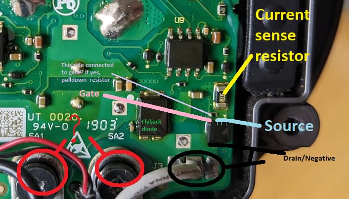
In the meantime I’ll base my assumption that this is an N-channel mosfet based on the circuit layout (it would ordinarily be easy to tell but Dyson are dicks and are using non standard wire colours) - I’m also basing the mosfet pinout on the circuit layout, surrounding components and logical reasoning.
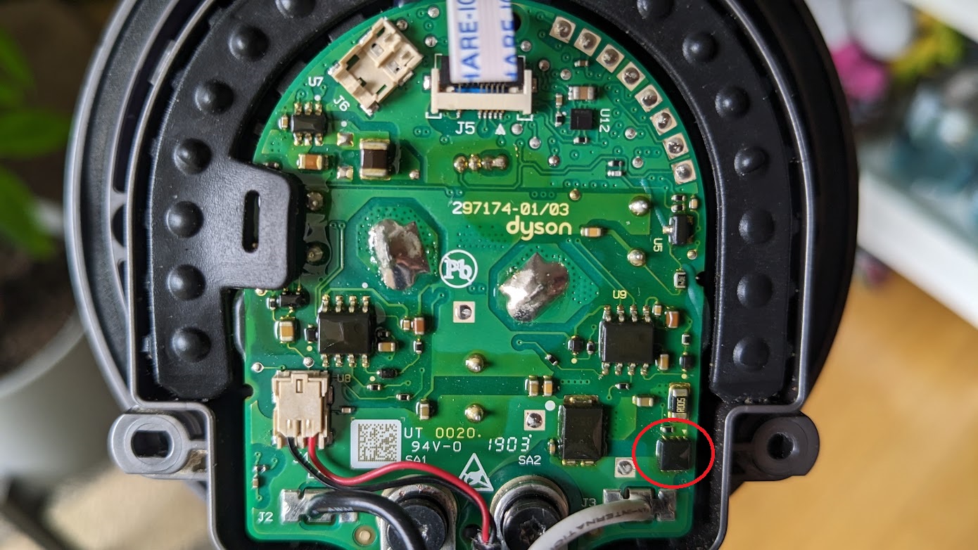
So a few things that I need confirmation on - can you confirm that the line I’ve circled in black (drain/negative) is one of the contacts going to the motor in question and can you also confirm which of the two I’ve circled in red are going to the second contact going to the motor? (it may be both but it’s a bit hard to tell from your image)
You can check and see if the mosfet is shorted out by disconnecting the battery and checking in resistance from gate to drain and gate to source. If it is shorted ignore the rest of this post, if it’s not shorted out, continue on 
Next, I need you to disconnect the battery, and connect that motor and hose etc, then I need you to measure the now known positive and negative (the two contacts which go to the motor), with one probe on red and the other on black and let me know the resistance of the motor?
You can see in my image in violet pointing to a resistor, can you confirm this side of the resistor has continuity to the gate (highlighted in pink) and then following this let me know the resistance of this resistor also.
Next you can actually measure stuff live  . you can hook up the battery again and can check the highlighted gate pin voltage when the tigger is pulled and see if it’s high (I don’t know what this will be, maybe 3.3 or 5V in working scenario)
Next you can put one probe on the source side (marked in light blue)and your other probe on the positive (whichever of the two you determined goes to the contact - maybe both) and measure the voltage - this is motor voltage (prior to the mosfet switching) … I’ve got no clue what this will be, maybe 12V or 18V (?) somewhere in that neighborhood. I don’t think you’d have to have to pull the trigger to get the voltage here but it really depends, so if you don’t get anything try pulling the trigger and see if you then do.
Also it’s important to note, that the “ground” I’ve higlighted is not common ground so when your taking your measurments you need to be doing so with your black probe on an actual common ground (which you should be able to identify by buzzing out a few of those bypass caps for confirmation [disconnect battery before doing this]) or by using the highlighted source side of the fet (assuming this is indeed an n-channel fet)
Also, caution, I remember when opening the older Dyson that on the other side of that board is some monster caps, and I can see three spots on that board with through hole pins which would match the footprint for those caps - and they are quite beefy (hopefully you can see the three sections I’m talking about) so prior to working on the board after disconnecting the battery, make sure to measure the voltage on these caps, if they are high discharge them with a resistor or worst case with a screwdriver with a plastic handle so you don’t get zapped.
Hope that all makese sense and if not just let me know