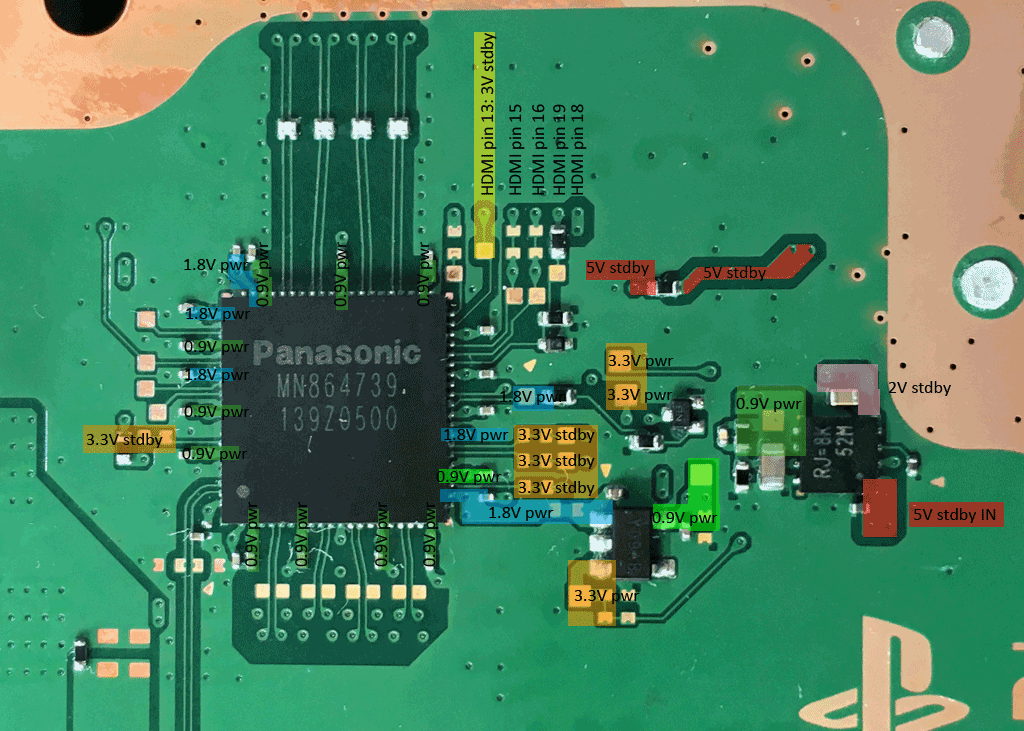
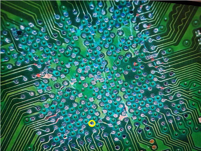
I checked the HDMI chip diode readings, and they seem fine. I checked the HDMI diode pins, and they’re all fine. The standby voltages are present.
I can’t check the Power on voltages of the HDMI chip because it turns off immediately after 1 second. Is it possible?
Even on the back, where there is 15JL I can’t measure any voltage at Power on because it turns off very quickly. I noticed with the thermal camera that the APU and RAM definitely don’t heat up but I think it depends on the fact that the process is immediately interrupted.
On this console, the SB 69gg was replaced and it was still dead until I found a 1uf capacitor shorted to SG 3.3V on the back. Removed it and boot sequence OK.
The 1µF capacitor had already been replaced and was reading the correct 3.29V in standby, but the console was still showing BLOD.
I later removed it because it was soldered crooked, and I haven’t reinstalled it yet.
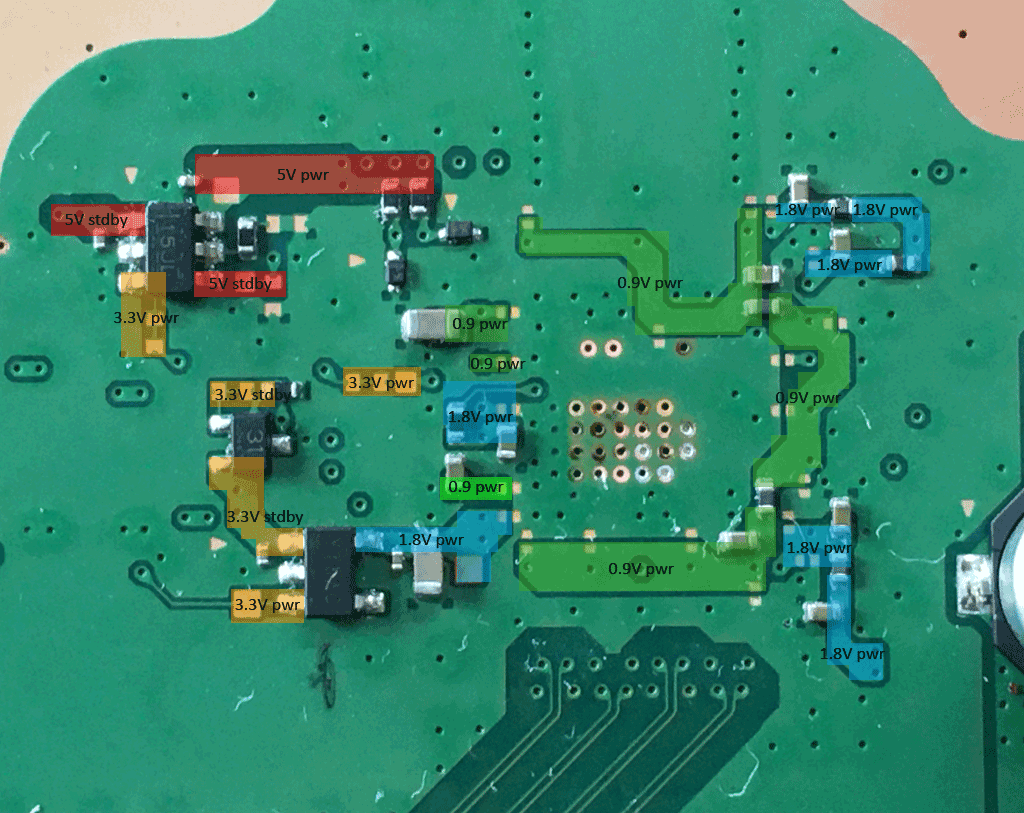
When I inject 3.3V into the EN pin of the 15JL, (first LDO) outputs 5V correctly.
When I inject 3.3V into the EN pin of the Y18 (the third LDO), I get the correct 1.8V output.
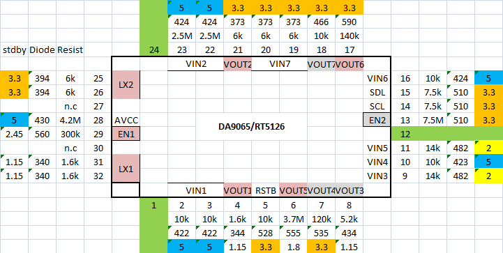
Regarding the DA9065, does PIN 13 being at 0V suggest a faulty Southbridge? I already replaced it, but it could still be defective. In fact, I have 0V on pins 7, 8 (during power-on), and 18.
I haven’t removed the Panasonic because I doubt it’s damaged. There are no shorts, the HDMI readings are perfect, and when injecting voltage into the 1.8V and 0.9V rails, there is no current draw. Additionally, it shows all the standby voltages correctly.
I think this behavior is normal. The PG2 (power group 2) power enable (EN2) signal is switched to low as soon as an issue appears. If the HDMI chip is outputting a error state, the EN2 is switched off or even not switched on by the southbridge.
5V switch/limiter (15JL) is ok.
1.8V_HDMI converter (Y18) is ok. → I would check if 1.8V are reaching all 1.8V pads at the HDMI chip. The 1.8V lines are separated by three ferrite beads. See the 1.8V patched areas on the right side of my last posted image. (Same for the 0.9V_HDMI lines which are patched together with two ferrite beads)
On the HDMI chip side are two other converter:
0.9V_HDMI_SB (neon green) generated from 1.8V (for checking 1.8V must be enabled too)
0.9V_HDMI (light green) generated from 5V
A shorted line is a nice indicator to find an issue but it is only one possibilty for a chip to fail.
C0810303 + 80810001 (216D) solved with Southbridge replacement.
Panasonic HDMI IC had normal diode readings with no shorts.
The Southbridge was not generating the EN signals for the HDMI regulators (15JL, etc.). After lifting the regulator outputs and injecting EN manually, all output voltages were correct, confirming the Southbridge as the root cause.