Game Card Slots - An Investigation

Hi all, over the last few years, I have accumulated a number of Switch game-card boards, some from switches I still need to fix, some I picked up “untested” on ebay, some where “working” from ali-express.
Most of them have some issue or other, but the most common seems to be touch that glitches, or only works on one side, or just doesn’t work at all.

So while this thread is here to ask for help, it is also here to provide as much information as I can on the ones I have in my possession in the hope we can get more information on the issues in general.

A) Working! It had previous issues due to some resistors having been knocked off the board, but these were replaced and it now functions. Will be used as a comparison.

B) So this board mostly works, but the bottom area of the screen is not being correctly detected. Pressing on the connector or chip does not improve it.

C) All areas are detected, but touches automatically release. Pressing on connector seems to fix it.

D) Similar to C, but even when pressed on, there is a line down the left side of the screen that is “skipped”. When not held on, it randomly touches in the top left had corner some times. Difficult to connect to motherboard.

E) Pins in connector have visible damage on the parts that go above the cable, but contact points all appear to be viable. No touch detected at all.

So, to start, the working one:
A)

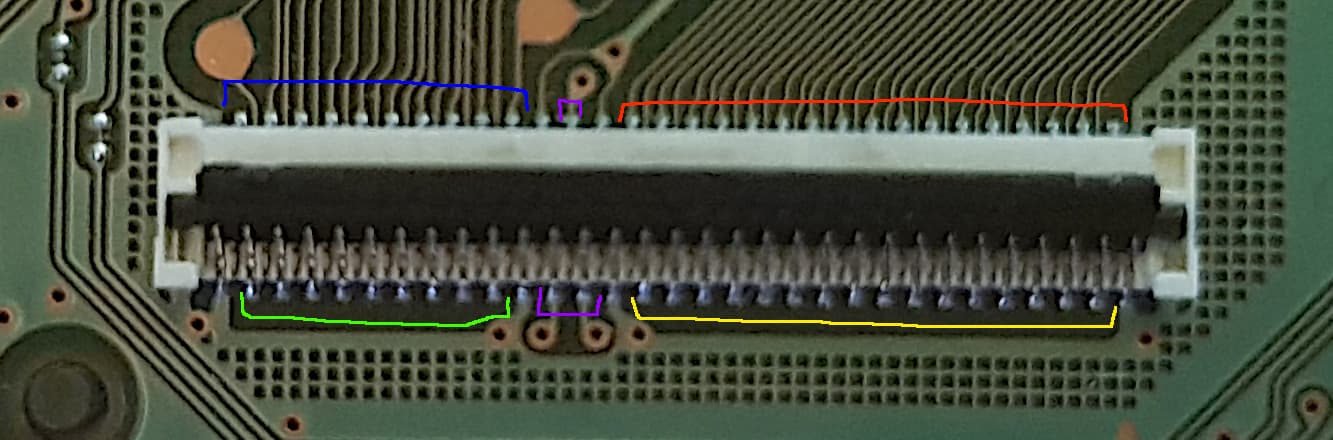
From what I can tell, when measuring in diode mode, the pins broadly fit into 5 sets.
Blue and Green) These are somewhere in the region of 0.72X. I would guess these are horizontal lines.
Red and Yellow) These are all 0.771, I would guess these are vertical lines.

Purple) Top and Left are 0.585, Right is 0.656. I have read in another post that these are connected to ground when some digitisers are connected. These measurements are without anything connected.

I will go through my faulty boards… probably tomorrow, and add them in.

So, starting off I just had a look at B), readings at the connector were all the same as the good board, but it did look a little dirty. After a good clean with a brush it worked fine, so presumably the issue was inside the connector .

Next, had a look at D), going through the connector pins, I wasn’t getting a reading on the top pin, 4th from the right. After adding some solder, that missing vertical line was working, but it was still glitchy if I wasn’t holding down on the connector. The lock on the connector is slightly burnt, so likely needs another new connector.

Next I looked at C), I was expecting to find the connector melted, but it looks fine, I did notice some dirt at the back of the connector, but cleaning it all out didnt make a difference. The left side of the screen works fine, and the improvement when pressed seems to happen when holding the right side of the connector. Readings at the red and yellow sections seem ok. Will continue with this one another day.

Had another go at D), changing the connector over. New connector looks good, but it now gives no response at all, so suspect the chip now has bridges under it. Yay…

Also had another look at E), noticing that the connector for the motherboard had some bent pins. Swapped that out, which went well, but no change.

Hi,

Many Touch isses occure, because the Version from the card Reader does not Match your Board Version.

Like the switch itself has a V1 and V2, the card readers also comes in these and if you use the wrong Version, the Touch does not work or is glitching.

Hi! Yeah, thats why I called this an investigation. I am somewhat hoping to gather enough information to work out what is different between the revisions. I heard before that someone ‘converted’ one by connecting some of the purple pins to ground. Which suggests it is a difference in the digitisers rather than the motherboard.
I am hoping that board E) is suffering from that, as then I can start playing with different digitisers and boards to see what helps.

I cant remember to saw Different Version of digitiziers. When I buy spare ones, they work with both versions.

In my experiments I’ve found no difference in the GC PCB at least afaict, So I assume the difference is on the chip on the board, so likely the internal FW (complete guess) - presumably this is how Hekate is identifying the digitizer type (?) maybe looking at the code could shed more light on this :thinking:

I’m not completely sure of this as I’m terrible at documenting my finds, the Chinese sellers are (or were) listing them as V1 and V2 digitizers, and If I remember right one had a letter/number code printed on the ribbon and the other had a bar/QR code printed on it instead, this I believe is what the specific revision of GC board/chip is expecting - I also believe there is aftermarket (or maybe even an OEM digitizer version :man_shrugging: ) which works with either and doesn’t matter which… as I say, I’m terrible at documenting but when touch only works around the extreme edges of the digitizer then that’s your cue the PCB isn’t compatiable with the digitizer installed and you should swap it for another which is what I typically do… unfortunately I never bother to check the code on the digitizer before doing it and just instead do it :smiley:

1 Like

Yeah same, so you mean we have both Different digitiziers as well as Different cartride versions, but both versions are compatible with the switch V1 and V2 Motherboards?

Yeah, I think so. And possibly new oem digitizers work with both versions.