Here’s another one for all the geniuses out there! Recently acquired an HAC-001 switch from a family member. They said they don’t know what happened to it, and has been in the closet since! So I hook it up to my USB-C ammeter with a 15V switch plug and find it drawing 15V at about .4A. After a bit, jumps to .6-.8A and hovers there for a bit. I can see the backlight is on and bright! However, I get no display. No nothing. Pop it into a dock and find that it displays just fine through there! Figure “OK, I know these things are super fragile, maybe they had some sort of repair done at some point, or dropped it”. Well I never did get anything out of them, and no repairs to speak of.
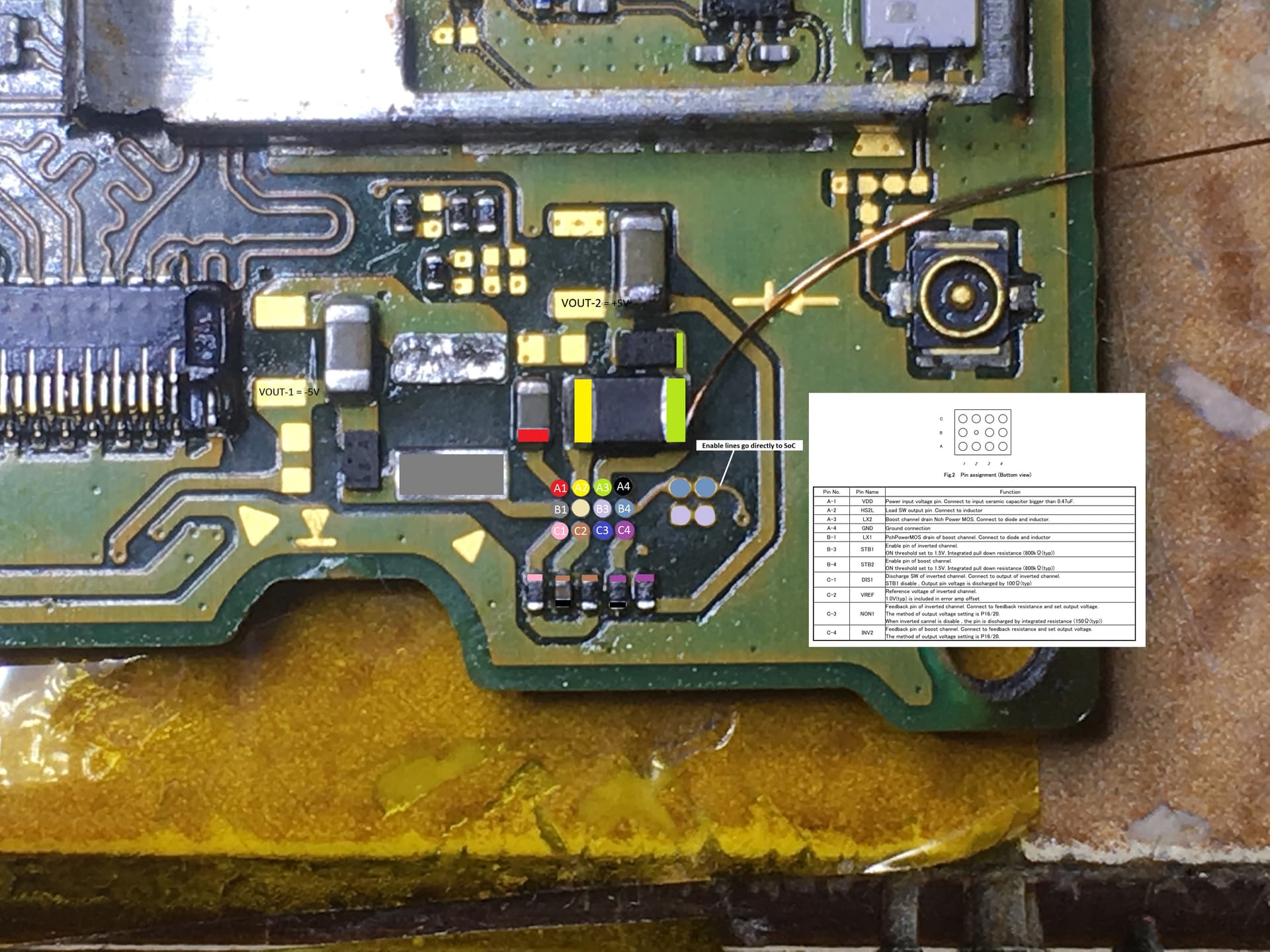
Here’s what I’ve done so far: Ordered a known good digitizer without the touch assembly. (CAREFULLY) removed the LCD ribbon and peeked inside and of course found nothing out of the ordinary. Found Insomniac’s photo of the 8316 driver and probed around there. With Insomniac’s picture, I’m finding that I’m getting 8316’s 1.8V trigger, but find no voltage on either VOUTs. I’m ALSO not finding voltage on 8316’s VDD. Here’s where I’m getting confused (this is not my profession, but something I love to learn about and maybe one day I’ll stop fixing cars and start fixing electronics), is it possible that the driver is shorted, bringing down it’s VDD? I tried to find a good schematic of the values around that driver but I’m not sure if the ones I’m looking at are indeed the correct values as I know there are some differences between revisions. Where to from here? Could 8316 but the actual root cause? Do I have a short on some other line that I’m blanking on?
You could test for this, just pop your meter over to resistance mode and plonk one of your probes on ground and the other at VDD and see
If i remember right VDD is your SYS rail (someone correct me I’m wrong) so you’d also wanna check that it has a connection all the way back to it’s origin (back at the BQ IC)
I made this crude image a while ago so perhaps it’s not clear enough but if the enables are high it means the SoC is telling the IC to enable it’s two outputs but if the chip isn’t getting it’s power (VDD) then it can’t
I would also be taking a very close look inside the LCD connector for bent pins as this very common, use your phone camera zoomed in in good lighting if you don’t have a microscope.
There is no schematics per se, every switch rev board is largely the same compent wise (excluding Lite and OLED) for the most part but layout changes are a thing so on some other rev boards for example, those two enable TP at 8316 IC might be at a diffferent location or some passives might be in a different location.
Ah, of course… Why didn’t I think of that! Geeez Severence! Back from the grind now. I’ve got OL on one side of the cap, and 0.8Ω on the other side. Assuming this is a capacitor to ground on the other side like I’ve seen on some other boards (still learnin’ )? If so, I suppose I’ll put it under the gun and see what pulling 8316 does.
Here’s what I know now: One side of the cap shows >1Ω on the north side (if referencing YOUR pic) and OL on the south side. Peeked inside the LCD connector with a USB microscope of questionable quality and really got in there, every pin looks nice and straight, back and front. No difference in very very slightly wiggling or lightly pressing down on the top of the connector with the LCD connected. Thinking my issue is gonna lay with 8316 VDD reading ZILCH.
Here’s the plan: New/used LCD showed today, I’ll pop that in for S&G and find no difference → Put the board back in enough to power on and see what voltage I find at the BQ IC (I’ll have to find another diagram and probe) → find either voltage or no voltage at BQ → Sleep!
Thanks a TON @Severence!! Seriously, every post I’ve read you’ve touched, and it shows a lot about the forum, and you as a person! I love to help others learn in my job, but I love learning from others about their professions more, and your patience is greatly appreciated!
Right, the component with one side connected to VDD (in red) is a bypass cap and it’s normal for the otherside to be connected to ground.
not out of the ordinary to read OL on SYS depending on meter limit/probe polarity
Leave this as a final step as I’ve just checked and VDD (VIN) on this IC is just SYS rail (so just think of them as one and the same) and as your getting a display in dock it suggests that SYS is present and working and nothing is pulling it down. So possibly you have an open line from one side of the board to the other. I suppose it could be an active short situation whereby SYS gets pulled low when the 8316 is enabled (for the LCD) when not in dock, thus pulling SYS low, but this would be very rare.
Specifically at that big “2R2” inductor nearby, watch out for dry flux which could prevent your probes from making good contact, one probe on ground and the other on either side of that inductor, you should get approx 4V, after disconnect battery/power and ensure you have continuity from that inductor back up to that cap connected to VDD of that IC, if it’s open we can troubleshoot further, if it’s closed and your not getting voltage there then you have a very unusual fault
NEWS! Ok, after a nice meal I’ve had a moment to sit. Here’s some new info →
VDD DOES have voltage, however… ONLY when the LCD is not connected! Taking measurements before and after the ribbon removal are completely different. I now have 5+V at both VOUTs AND 4.xV at A1… Of course, after becoming somewhat excited and going back and forth, the white piece (blanking on the name) that compresses the pins to the ribbon broke off at the right pivot… SO I think if diagnostics ever taught me anything. That’s a confirmation of a either a faulty LCD connector (for sure now lol), or a faulty LCD. Of which I have one and not the other! Of course, now that I have an LCD here, I now can’t confirm until I replace the connector.
That’d be correct! 6 years now, second in command at a local shop of 4 techs. I do most of the electrical diagnostics and play with scopes all day Some certs in Toyota Hybrid, some security stuff and a few ASE certs to go with!
Interesting, so it seems like the LCD was at fault and it was subsequently pulling SYS down by way of the 8316 IC and working when docked presumably because the 8316 outputs are disabled when docked.
These connectors are the worst. If it’s just the “hinge” portion that’s broke, and as long as the rest of the body of the latch is slipped over the pins and putting pressure on all of them when closed then it will be fine, just be extra careful when folding it back down as it will want to slide off the pins and if that happens you may as well replace it at that point or spend ages trying to slip it back over without bending the pins In future, try only folding the latch from the middle while pushing it inwards if that makes sense
Sweet. What do you use the scope for out of interest?
Yay! Well I’ll try popping the white piece back on and see if that goes smoothly!
I mainly use the scope for network diagnostics. Lotta modules in todays average vehicle. I just finished a class in controller area network (CAN) and found that really interesting. CAN would be a good example of a scope scenario. Say a module stops working, or sets a “communication” code, usually pointing fingers at another control unit it’s not able to talk to, etc. Well there’s two lines in a CAN network we’d look at, CAN high and CAN low. Mainly voltages higher or lower than it’s reference, and watching for any sign of corruption or dirty sine waves. Or seeing shorts to power, shorts to ground, anything that takes down a network completely a scope is a nice tool to have!
Interesting, if I remember right a lot of the newer vehicles these days are doing away with the OBD port (?) so I imagine knowing how to use a scope and get in there “manually” and having the knowledge to decode the data on the CAN bus is all the more valuable. Though I imagine much like other areas of the repair industry, as time wears on, companies will likely get trickier and start changing to encrypted and/or non standard protocols in the “name of security” Hopefully govermental protections are in place or put in place before this happens
Yes! Newer companies like Tesla and I think Polestar, and likely other manufactures that are solely electric have proprietary diagnostic ports as OBD was federal law for emissions.
Funny you should mention encryption in 2016 Chrysler began implementing a security gateway that requires a login to access/scan the rest of the individual modules. Now, CAN is typically on two pins on the OBD port, and most if not all will grant you access to a “global” scan. Meaning you could just go plug in any basic code reader and read a code, but it would only have access to read codes from say the engine control module, or the transmission control module, or maybe SRS. The security gateway can be bypassed… but I think that’s a tight secret that I don’t know of! It’s subscription based now, granted a yearly license for any one shop through a third party LOL!
Anyway, didn’t get the plastic piece back on, ended up removing the connector and I’ll have a couple here in a few days!