Hi everyone,
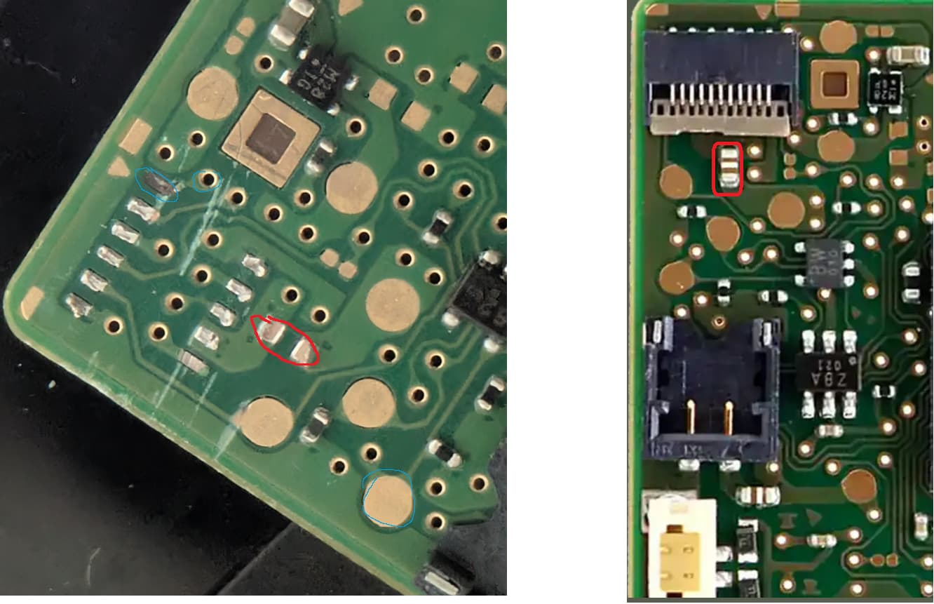
I’m currently working on repairing a Joy-Con controller. While replacing the flex cable connector, I cleaned off the old pads — most of them are still intact. However, I’m not sure which pins on the flex cable are responsible for power (VCC and GND) and which ones handle the data lines.
Does anyone have a pinout diagram, a wiring schematic, or could tell me which pads on the board are for power and which for data? Even a clear photo of a working board with the flex cable connected would be super helpful.
Really appreciate any help or tips you can share!
Thanks a lot in advance,
Noha
photos.googlecom/share/AF1QipPQPp500kNGwcerj0dBdKmAwj0sIqTasPfQ7PumPK_bKuzd1SwKeEIC1o74GYTtBQ?key=dFlpN3JMSUxKQXBsLTdpRm9wSDhjLS1DRHRuSFl3
sorry for a reason I only can upload pictures like that add a dot .com