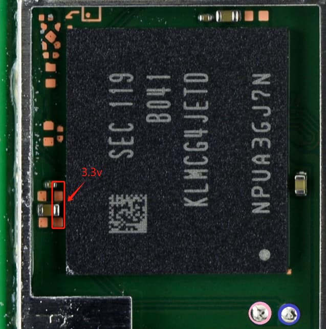
It’s any cap which is on 3V3PDR, you can verify this on the other board, either by buzzing out in continuity or by measuring voltage, if you measure 3.3V then chances are it 3V3PDR (in most cases) - you just looking to play the old hot and cold game, (you know when you were a kid, getting warmer, warmer still, hot, red hot etc) measuring the lowest reading at the cap by the EMMC (for example) would indicate in most cases it’s the EMMC IC at fault, and likewise, if you measured the lowest reading at the cap by the M92 IC then it’d likely be indicating that IC is at fault and so on
Is the short to ground on 3V3PDR still present with it removed?
I imagine he is reccomending this in modchip cases as a result of the jig / slip in wire methods as they pose a high chance the user will screw up the underlying balls in the process.
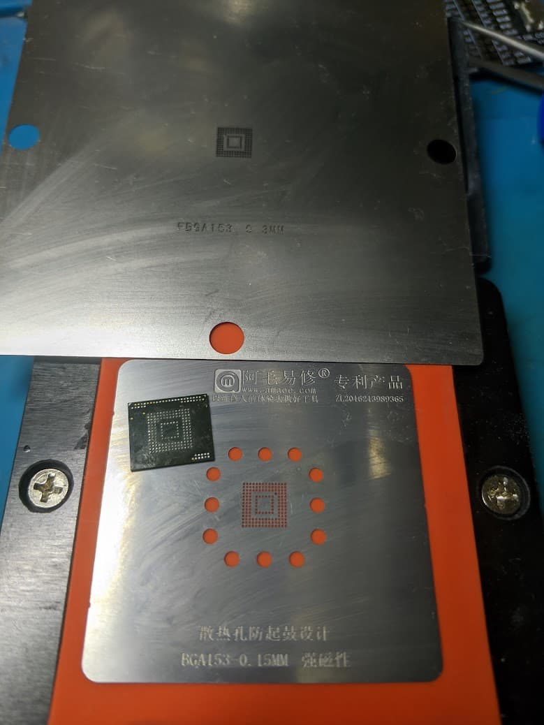
I think EMMC balls are smaller than this regardless.
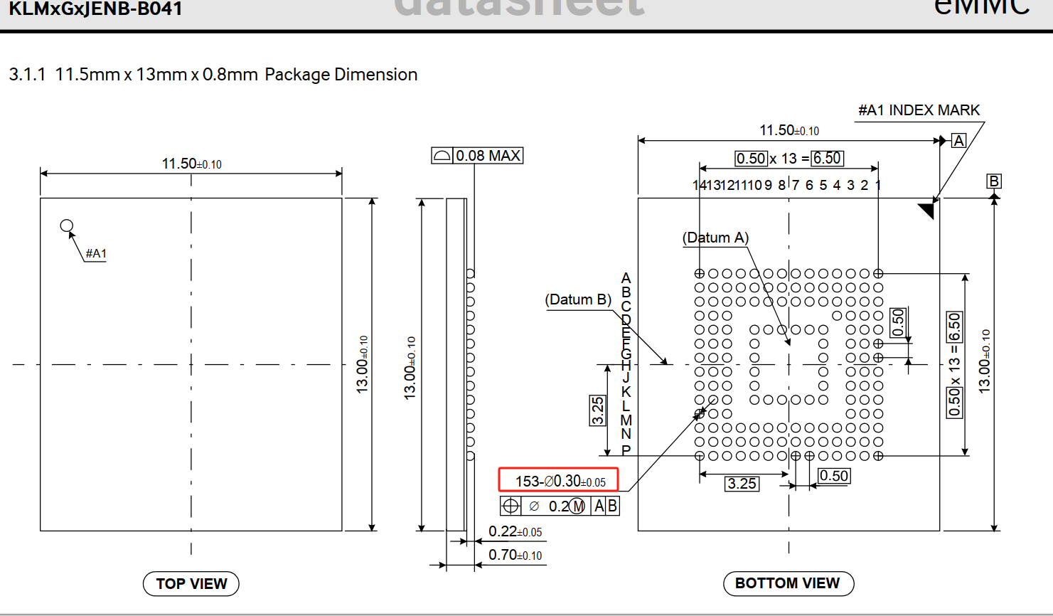
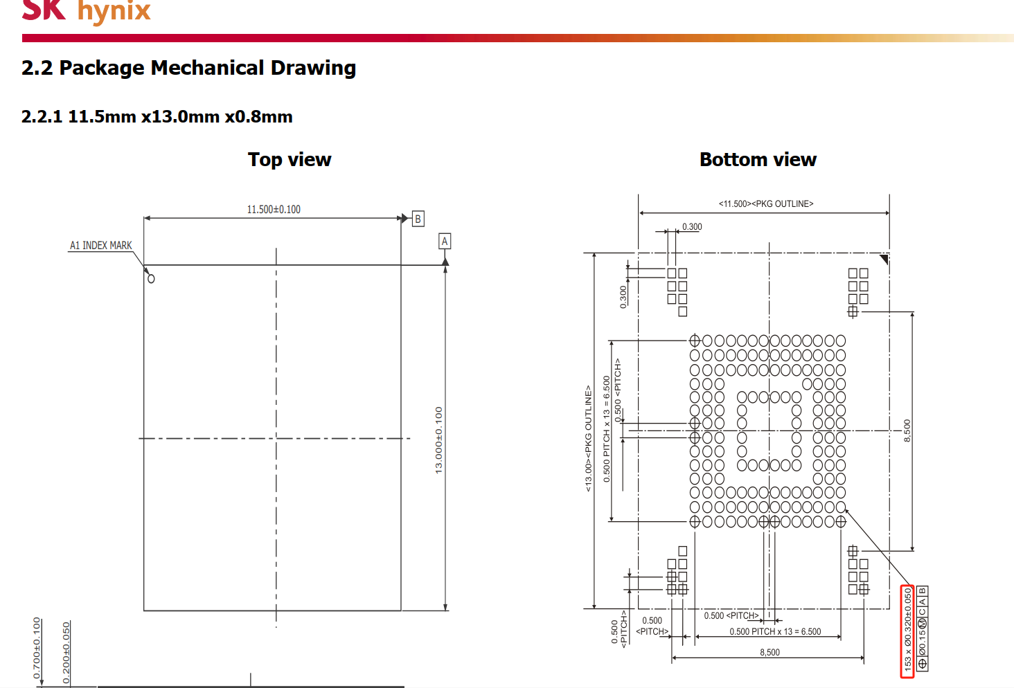
I went through a fair few datasheets a long while back and if I remember correctly some were calling for 0.25 and some 0.3 but I could only find a couple of datasheets which actually specified this. I suppose it depends on the brand and pad land size too.
I guess with the +/- 0.05 it can be anywhere from 0.25 to 0.35, though I’d guestimate it’s closer to 0.25 when comparing to a stock reballed EMMC IC as 0.35 balls look a fair margin too big when comparing
Datasheet seems to specify max ball height too which suggest you should be aiming towards the lower end of the ball size margin (so balls don’t bleed together I’d imagine)
I’ve taken measurements on the capacitor indicated by jkyoho next to the NAND, and I’m not getting 3.3V. I think that since the MAX77801 IC isn’t present, the 3.3V line isn’t functioning. However, I am getting 1V on the
capacitor on the other side.
http s://ibb. co/ z8sM84X
On the side of the MAX77801 IC, I’m not getting 3.3V to the capacitors next to it, but I am getting 4.1V to the one I’m pointing to here:
http s://ibb. co/ mTYsG7t
Is it normal to have 4.1V here? Shouldn’t it be 3.3V? Or does it fall within the tolerance limits? Wow, knowing about the solder balls, I won’t use them—I’m not sure where I saw that they needed to be that size. Is there an effective way to check if the 3.3V line is shorted to ground?
Thanks to both of you for telling me about the size of the balls; this way, I’ll avoid reballing with those. I guess I’ll order some 0.3mm ones.
4.1V comes from battery, it is normal and value varies from the battery %.
0V on those 2 big caps is ideal when you dont have the ic that convers the battery voltages to 3.3v.
Measure the 3.3v line( at the 2x big caps)resistance to ground with and without NAND solder on. You might have short either on the NAND or somewhere
Ok, with the NAND removed, the same measurement gives me around 88K of resistance, so it seems you’re right. Now, after removing the NAND, I see that there are two pads that are connected, and I’m not sure if that’s how it should be.
looking at the trace it looks like they’re connected
Check the datasheet for the EMMC and see which pads correspond with the 3V3PDR rail, typically it will be called VCC, check that pad with one probe and a ground pad with another probe and see what the resistance is directly on the EMMC IC. you can also check VCCQ (1V8PDR) and check that too.
This will just verify if the EMMC is good/bad (for the most part) . if it measures fine then it suggest a soldering / reflow issue and you should be able to reball (properly) and re-install, if it’s shorted then it’s bad news i’m afraid
Now, if I connect the board to a 5V USB, I see that on the two 3.3V capacitors, I’m getting 0.470V. I suppose that’s normal with the MAX77801 IC missing, right?
Thank you very much for your support! I also think the NAND is fine; maybe it shifted while soldering. I’ll try again.
Don’t think that way! Learning languages is always a good thing, so you don’t have to rely on a translator or ChatGPT all the time.
I think I should also replace the inductor I initially mentioned. I removed it, and after examining it closely, I see that it’s slightly broken on one side. Does anyone know the values of this component? If it’s present on a Switch V1 or V2 board, that would be perfect—I have a couple of donor boards. I’m attaching an image of the inductor
True, though I imagine it’s only a matter of time before AI live translation in person becomes a thing, even using your own voice
Datasheet for the Max IC calls for 1 μH
If you go to page 16 it even tells you the reccommended brands too.
The inductor by the ENXX IC (near the Realtek audio IC) on original rev bards is also the same and you should be able to use that (provided it’s the same size physically)
"Ohhh, great! Thank you so much! I’ve found it now; it seems different on the V1. The IC chip I have next to it is labeled ENRN in the original board (V2). I can’t use this as a replacement for the MAX77801, right? I can’t find any information about this IC online.
AI is evolving very quickly—who knows how far we’ll go?