Hello everyone. I’m just starting out with Nintendo Switch repair, and I’m facing the following problem. After a failed installation of Picofly, the Nintendo won’t start. Not even the lights on the Picofly chip turn on. I’ve found an inductor that heats up near the audio chip and has continuity between its ends. Could this be the cause of it not turning on? I think that when I connected the 3.3v flex cable, I might have bridged the two capacitors, and I also found another bridge between this inductor and another capacitor. Any help would be appreciated. Thank you very much.
This is the inductor
http s://ibb. co/xJPLSQ4
show a picture of the bridge you made after removing the flexcable.
For a inductor, it is NORMAL having continuity when you probing them from one end to the other, inductor is just like a wire, low resistance(closed to 0 when measuring in low frequency).
You don’t even need to replace the inductor since you said it has continuity between its ends. Inductor failed when there is NO CONTINUITY.
What a rookie mistake, I thought I had located the short… I removed the bridge, it was connected to a capacitor right next to it. I’ll attach a photo tomorrow. I think the problem must be around there, with a thermal camera I saw the inductor flashing intermittently. That’s why when I saw continuity I thought it was the problem. Could the issue be the power regulator IC? Thank you very much for teaching me. Best regards.
I could image you probly using a large blade type iron and working on those area. Hard to tell what goes wrong without clear pictures. You could also do some diode reading measures around the inductor and capacitors around the place you worked on.
This is the third time I’ve installed a Picofly on an OLED; the other two went fine without any issues. This one was for my eldest son, and everything has gone wrong from the start. I burned the resistor at the CMD point (purple screen), replaced it, and in the process, something else got damaged because now neither the purple screen nor the Picofly lights turn on. I removed the flex and took a picture, marking where I made the bridge. I’m not getting 3.3V to the capacitors further up where the Picofly flex connects to provide the 3.3V. I’ve measured the entire area and don’t see any shorts. It’s fun to learn, but my son hasn’t spoken to me since then. I wish I could fix it :-
http s:// ibb. co/ YQ5XqqF
Not sure if that means the chip is broken(blue circle) or just some cold solder laying on top of the chip. I dont see any bridge of main issue would cause issue on this area so far.(Hidden east egg on the bonus resistor on the inductor marked in green)
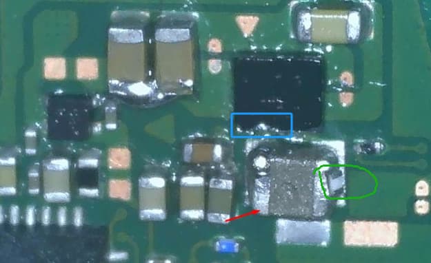
Haha, I hadn’t noticed the Easter egg. It’s one of the resistors from the cmd point that I lost while replacing it, luckily they come in packs of 100. Most likely the chip is broken, could that cause the 3.3V not to reach the capacitors further up?
I really appreciate your lessons, thanks!
well yes, when chip is broken, 3.3v no long been generated
Thank you very much for your help. Now I’m more certain that the problem is the MAX7781. I’ve ordered one, and I’ll post the results later. By any chance, does the classic Nintendo Switch have this chip? I have a couple of donor boards.
I’m watching this video, and in my case, I don’t have a short on those capacitors, so I hope that after replacing the MAX7781, I’ll get the 3.3V back.
https:// youtube .com/watch?v=oybLHsejoMo
You’d replace that capacitor with the damaged end-cap as a matter of course, as it likely will fail eventually.
Besides, inductor might not be getting hot as a result of a direct short on 3V3PDR but rather as a result of the IC itself or because something else downstream (for example something which 3V3PDR provides as something elses input) is shorted, thus, current goes up, heat is generated as a result. Primary rail checks are reccommended (search the forum if your not sure)
Thanks for the suggestion. I’ll follow your advice. Can you confirm if it’s a 22µF 0603 capacitor? I hope that when the IC arrives, I’ll have good news to share
yes, big caps are 22uF.
FYI that YTber seems quite amateur
Thanks, I’ve also ordered some of those. I’m also very much an amateur, and those videos teach me a lot as well. ![]() I’m learning a lot, but I still have a lot left to learn. Thank you so much!
I’m learning a lot, but I still have a lot left to learn. Thank you so much!
I have some updates. While waiting to receive the IC, I removed the one that was supposedly bad and did a reballing on it. After putting it back, I recovered the 3.3V, and the Picofly LEDs turned on. However, when I reinstalled the NAND and tried to boot up, the 3.3V was gone again. I think that when I soldered the NAND, since it’s right on the other side, the problematic IC got loosened. I did reballing on the Max77801 again, but it still didn’t work. The Max77801 actually looks pretty bad. It’s difficult to align because it only has one reference point. Any tips for installing it?
You removed the EMMC IC? if yes then presumably, best guess, you shorted something out on 3V3PDR on EMMC reinstall, hence why you weren’t measuring 3.3V (again just my best guess) did you check resistance to ground on this rail prior to powering on? I suppose the Max IC could still be the issue as opposed to the EMMC, but given the sequence I’m leaning more towards the EMMC.
How are you reballing these IC’s?
Hello, my friend! No, the short was already there before removing the NAND; I removed it to rule out that it was a problem with the NAND. Without the NAND, I’ve confirmed that I’m getting 3.3V to the 22µF capacitors where the Picofly connects—I’ve tested this on another console as well. If I measure these capacitors on another Nintendo without the NAND, I get around 0.800 in diode mode, but on this one, I get 0.002, so something is wrong. For reballing the NAND, I have a BGA153 stencil, and for the MAX77801, I have another stencil for this chip. Thanks for the response!
I suppose you’ve got to do the reverse again and pull the Max IC and see if the short on 3V3PDR clears while the EMMC is present.
Alternatively switch your meter to resistance, find a consistent ground (USB pads are a good choice) and see which area where 3V3PDR shows up is lowest to identify the culprit, so, for example, stick your black probe on ground, and then put your red at those caps by the Max IC which are on 3V3PDR and note the reading, do the same at the cap next to the EMMC IC and do the same, you could also do it at the M92 IC and SD card etc etc and then see which reading is the lowest, if it’s by that max IC then you can safely say it’s the Max IC at fault and so on, (this all assumes that your meter has the resolution to do this mind)
Also to add, reballing the EMMC is tricky for beginners, as the ball size is so small and the IC is so thin… solder paste results in considerably smaller balls than the stock balls / preformed solder balls which can cause issues come reflow time, that and solder paste isn’t as consistent size wise across the array (even on a perfect paste reball)
Could you point out which capacitor it is? I’m attaching an image of the NAND. I’ve done reballing on EMMCs several times; I’ve damaged some in the process, but I think they’re done correctly. In this video by Sthetix, he recommends reballing the NAND:
http s://www .youtube. com/ watch?v=rUMATSjFn-0
I have 0.35 solder balls, but I like how it turns out with paste for now
I’ve thrown the MAX77801 chip in the trash; it was in very bad shape, so I’ll have to wait for the new one to arrive.
My NAND: http s://ibb. co/ nQ2PBj4