Sorry for possible grammar mistakes, English is not my first language.
I got a broken switch from ebay that seemed to be an easy fix but unfortunately i was wrong…
After changing the battery the switch booted fine but the right joycon does not connect (not even charing).
I cant connect them (tried two joycons, one of them brand new) wireless because the switch got a factory reset before selling.
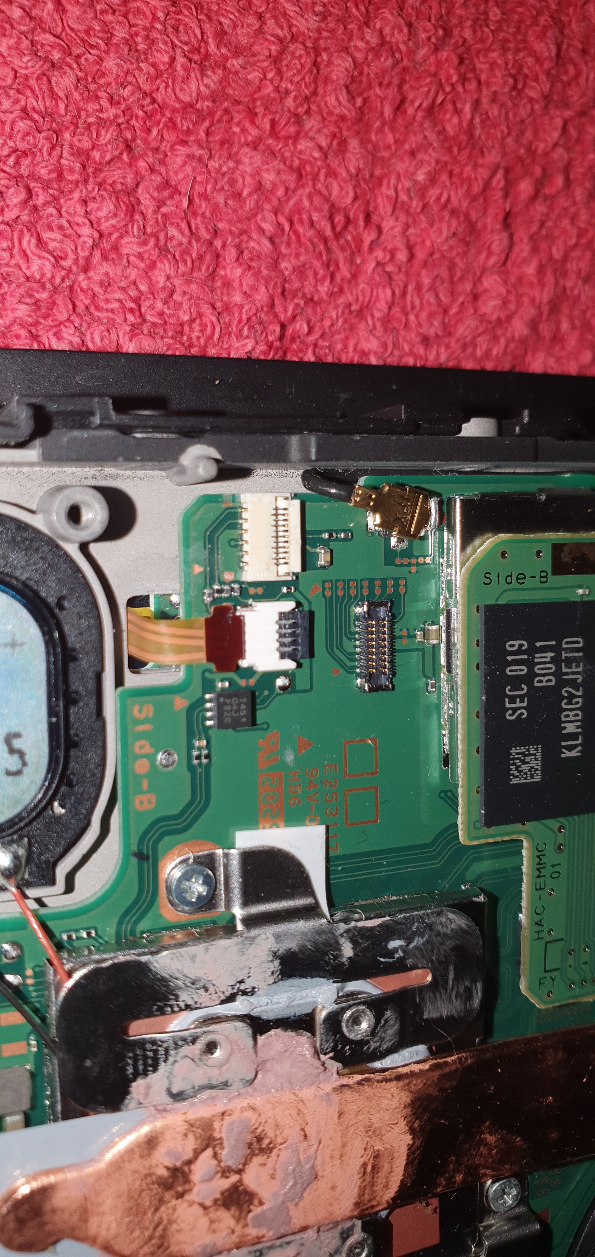
Port and Motherboard looking perfect, i have no clue what can cause this. I can Post Pictures if you want to.
I have now checked some caps and nothing is shorting so far. Got a new joycon rail in the mail today but the right joycon still doesn’t connect or gets charged… I really don’t have any clue how to fix this
Hi!
First question, is it both that do not connect or just one of them?
If the other one is able to connect fine, it most likely something in the area around the joycon connector.
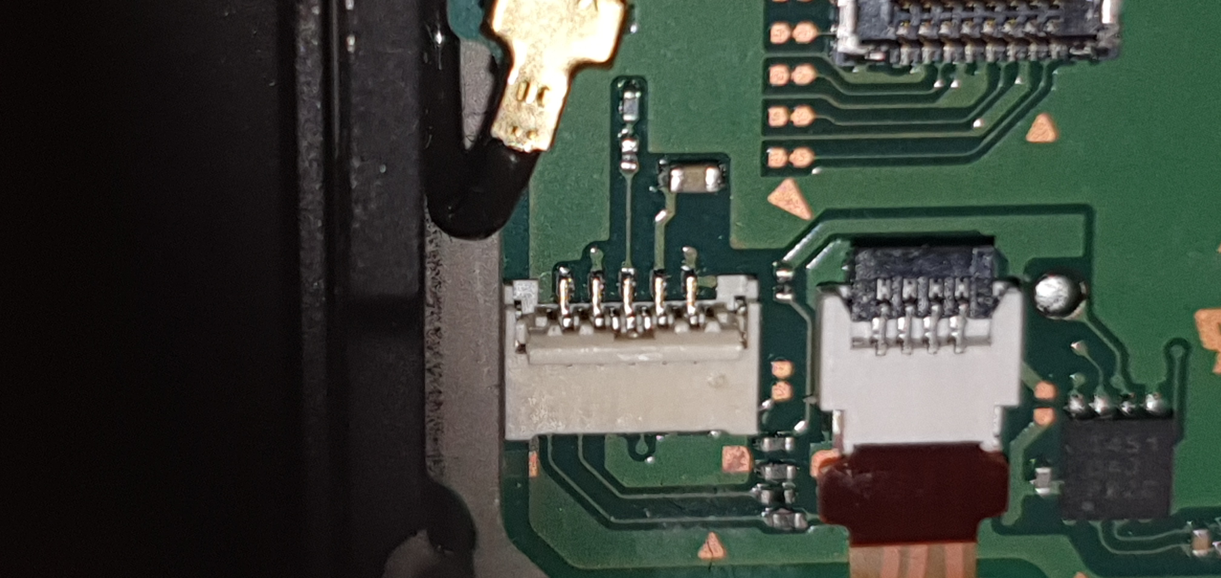
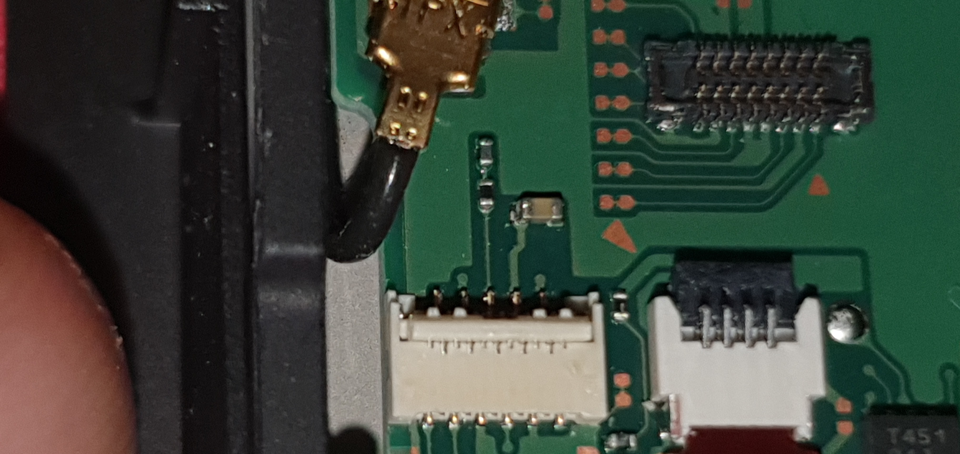
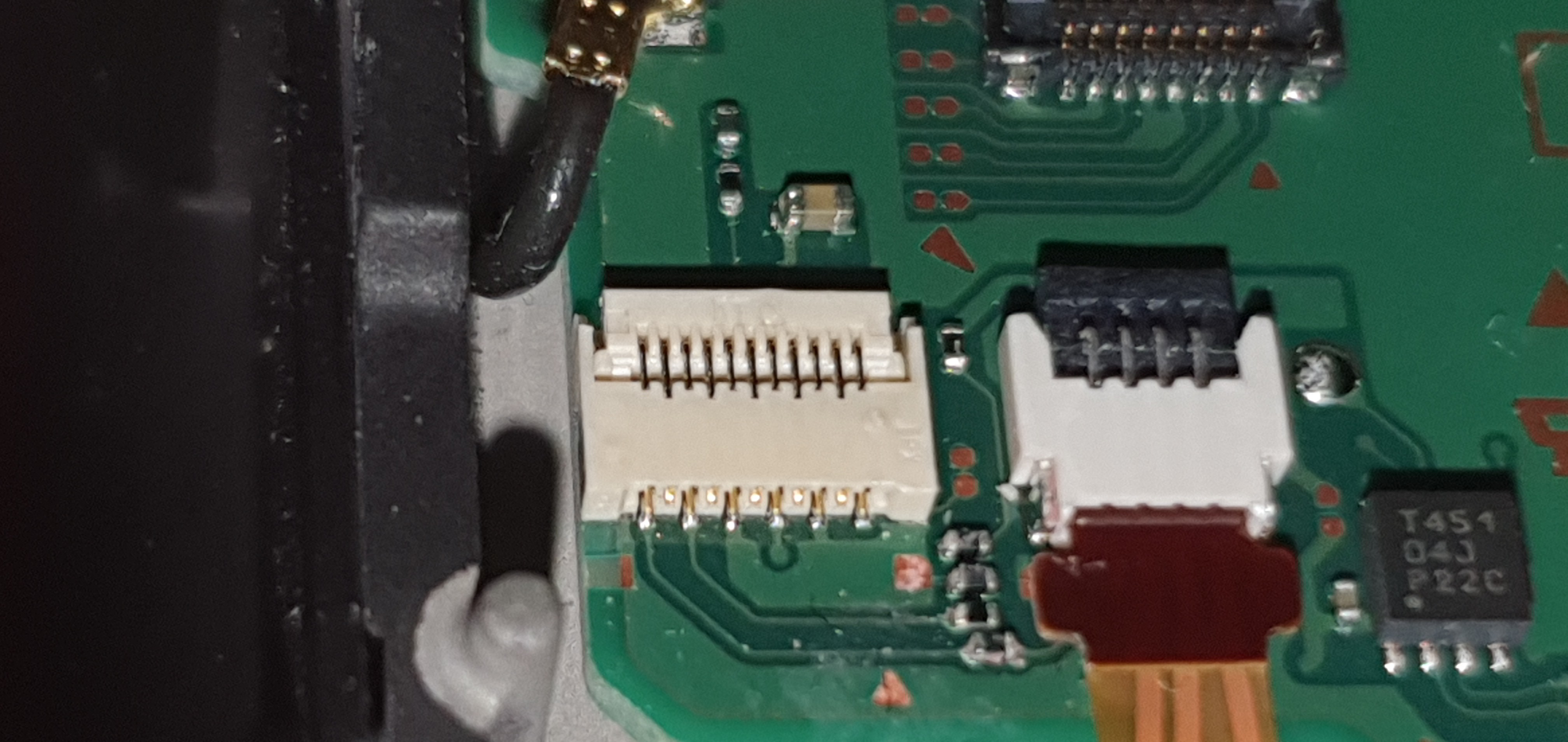
I would start by making sure that the connector looks fine and that none of the pins have come loose.
Next I would attach a joycon (or just a spare rail if you have one) and check continuity all the way through from the board to the joycon.
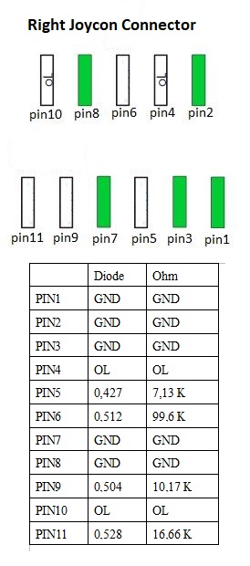
If all of this checks out, then we move on to diode / resistance readings at the connector pins to see if something has failed.
There is a thread on here somewhere that covers the readings around that connector but I can’t find it anywhere. If you get a diode and resistance readings to ground, in both polarities, and for all of the pins I will compare them against some boards I have here when I get a chance.
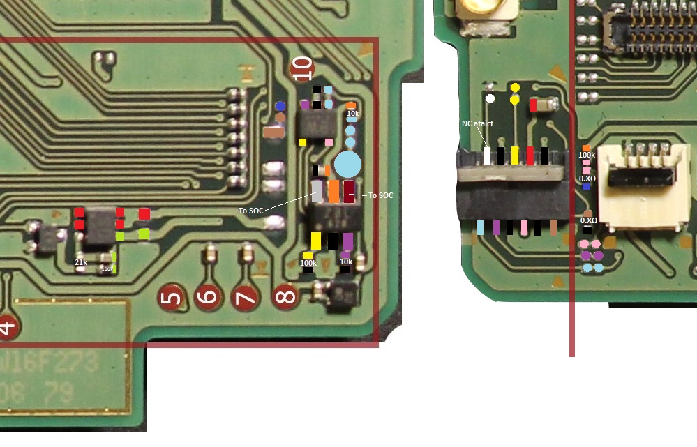
So, resistance wise, pin 5 seems the most different, which isnt great news, as it connects to the SOC.
Pin 6, which is also off also connects to the SOC.