Hey,
I purchased a Nintendo Switch with a joycon pairing issue (won’t register joycons).
Initially when I opened the Switch, some ribbon cables were disconnected which I found strange. After reconnecting the ribbon cables, the left joycon rail started to smoke. It burnt out the chip on the rail itself.
Fast forward a few weeks, new joycon rails arrive.
Now the right joycon is detected, but the left joycon is not (battery side).
The controller does not appear to be charging, tried a known-good controller and still no-go.
Pulled the board out, no signs of corrosion, checked caps on the left rail circuit, but no evidence of anything shorting. I’m kind of at a loss here.
Because there’s no schematic it’s difficult to track where the left joycon rail is going (circuit wise).
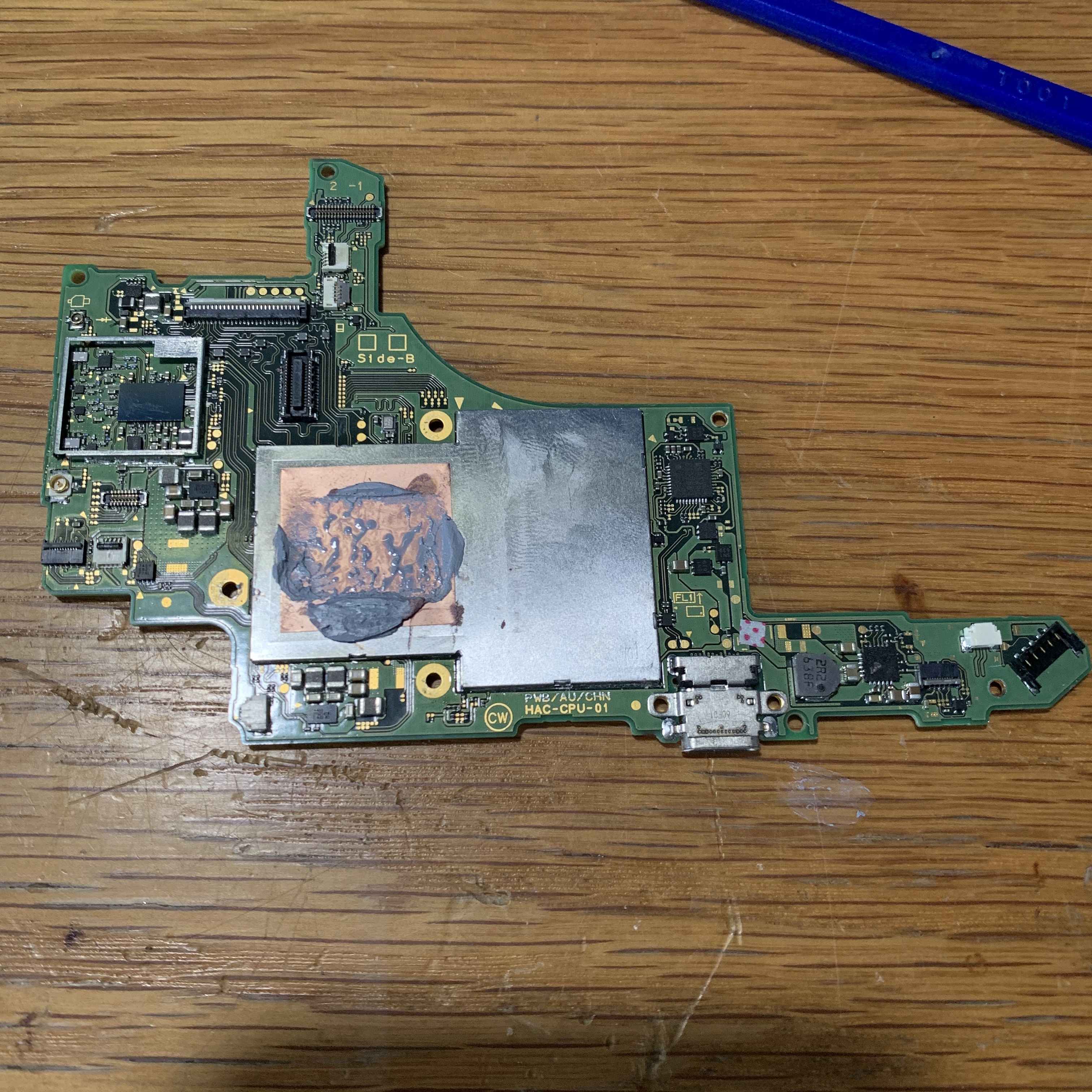
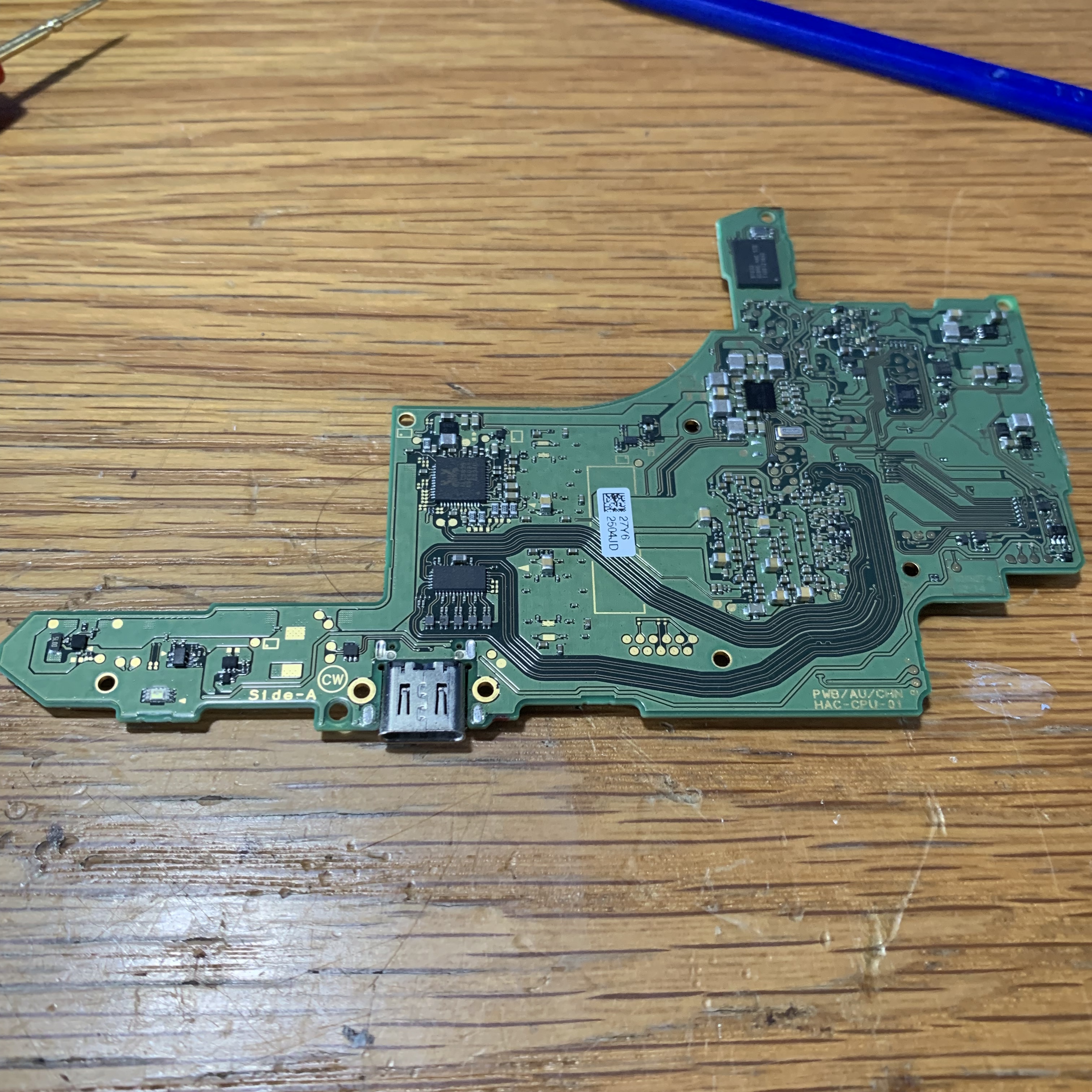
I have attached a photo of the board, front & rear.
Any further assistance or insight would be greatly appreciated.
This is certainly a strange one. I’m not sure I’ve seen a problem like this before. I don’t have any schematics or anything and I haven’t dealt with this issue so I can’t give you any answers here but hopefully someone else will be able to help you out.
1 Like
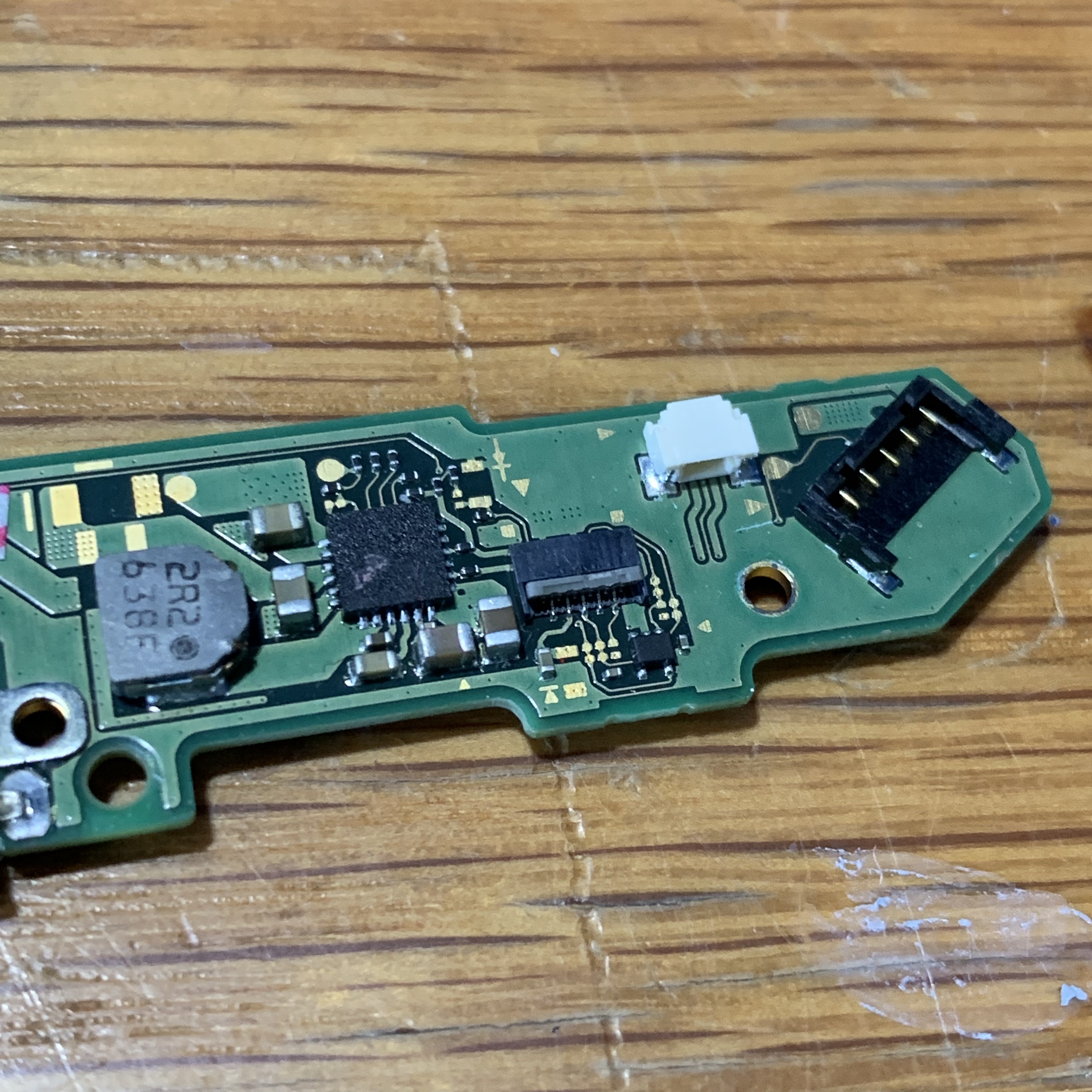
4th picture shows a chip with a crater in it that might be your issue mate
Hey there,
The chip PinkLightning is talking about indeed looks a bit suspicious. But, the chip is actually the chip responsible for charging the battery. It’s a Texas Instruments BQ24193. So to my understanding it’s not joycon-related. But, I don’t know, but maybe it’s also responsible for charging the joycon batteries.
The IC itself is available widely and here in Europe it costs like 3-4 Euros if you buy a single one. If you’re experienced enough, try changing it.
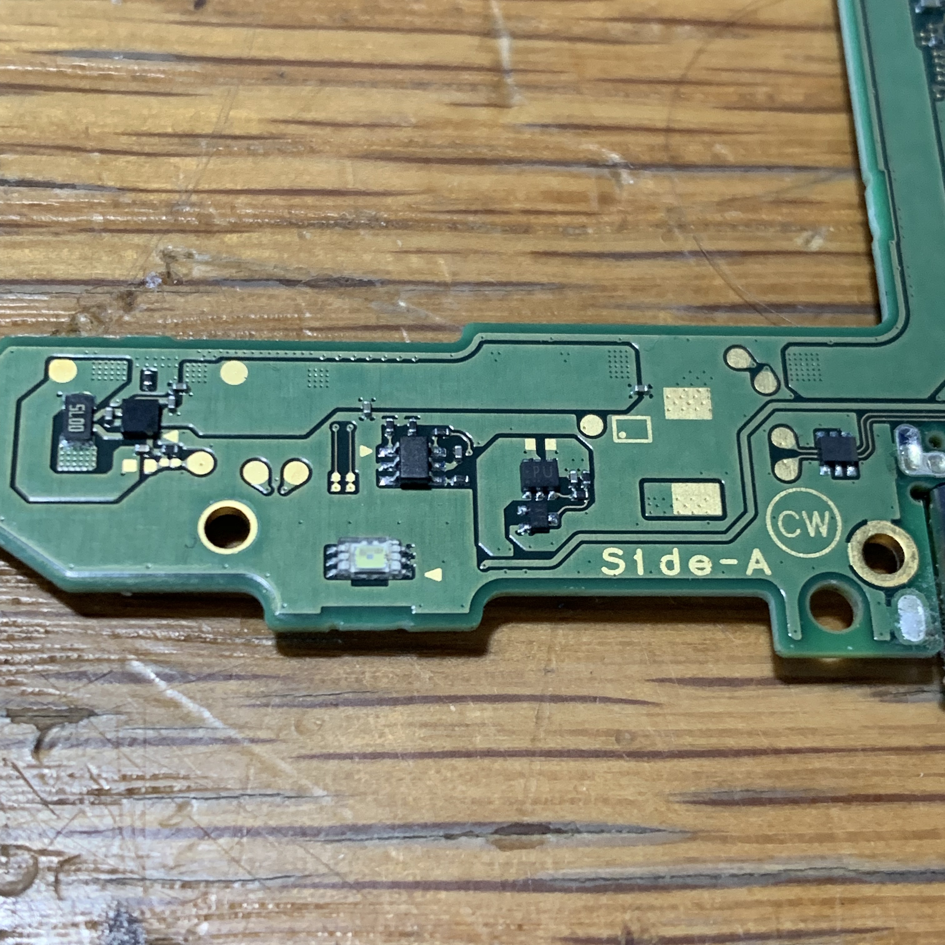
Or, maybe take a look into the 6-leaded vertical IC in the middle of the 3rd picture. Position-wise it may also be related.
Are you referring to the largest chip in the 4th pic? (The charge IC?) If so, it’s not a crater, it was a dob of some marker the camera didn’t pick up well. The console charges fine as well, so I can’t see it being a charge IC issue, unless one of the legs is not pushing out voltage to the joycon rail which may be a possibility, it appears the joycon rail passes thru the charge IC.
I might check voltages going into the joycon connector, I reckon it would be something ~3v-3.7v.
Hey there,
To me it also looks like the some joycon lines (power rails?) go through the charge IC.
Just took a deeper look at the charge IC’s datasheet (BQ24193). Seems like indeed it is able to charge a battery and additionally generate a separate, stabilised supply voltage for other devices. So, might actually be that it also generates the supply voltage for the joycon(s). Datasheet says that voltage is between 3.5 V and 4.35 V, depending on the configuration. So you should be able to measure that on one side of the big inductor and on the joycon connector.
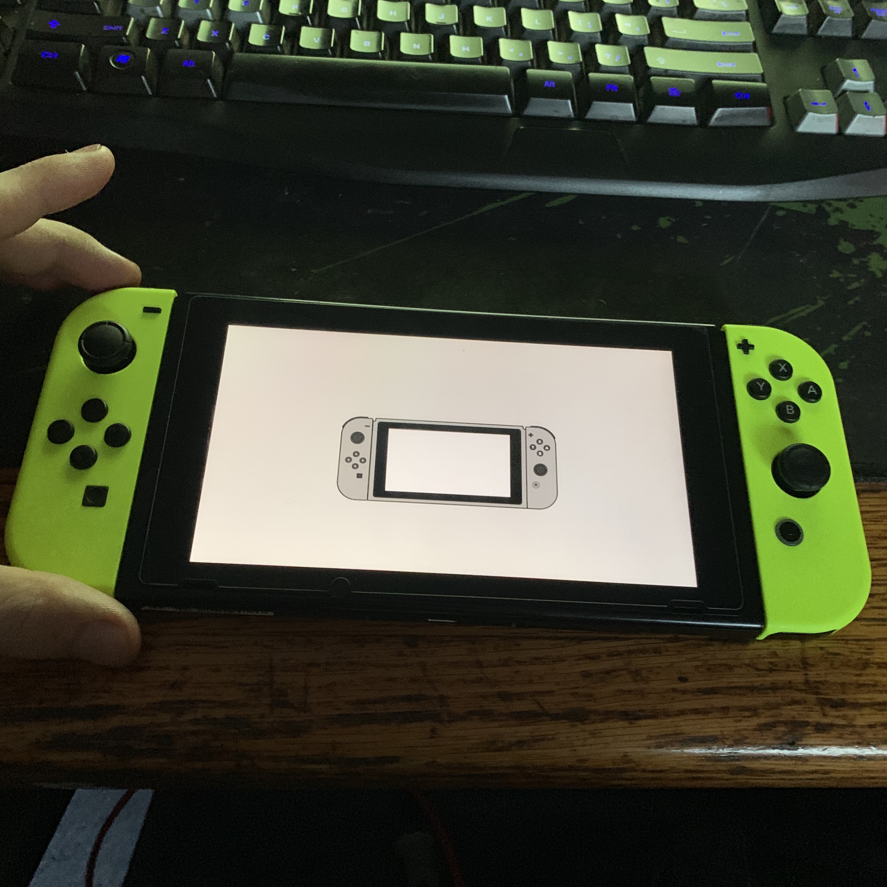
Cheers. I have just noticed, while on the initial joycon pairing screen, although there is no animation on the left joystick when connected, if I press the ZL trigger, the sound is coming through on the console. So it is registering the joycon buttons, but maybe there is a dataline issue with handshake or something. Upon leaving a flat joycon in the left rail, it will also charge it. The plot thickens. I will check BQ24193, but I am suspecting the issue is somewhere else. I’ll also try replacing with another joycon rail, as maybe it was just another faulty rail.
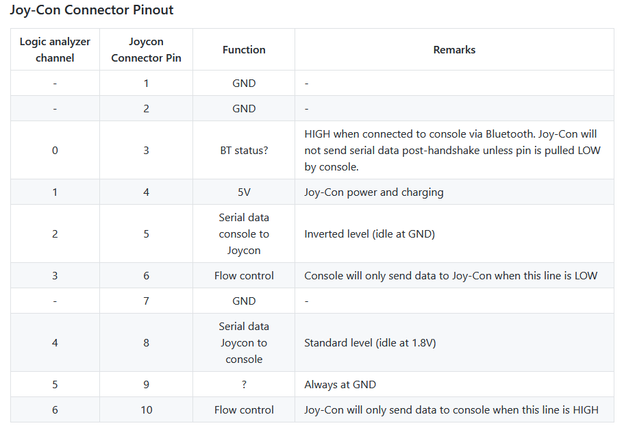
I also found a pinout for the joycon, it seems that PIN 1+2 are ground, but in my case PIN 3 is shorting to ground. It looks like it is a data line, so maybe that could also be the issue. I’ll have to trace where pin 3 is going.
EDIT: Further to this, I just tried booting into recovery mode, and left joycon works. I’ll try restore factory settings, but it doesn’t seem like a software issue to me.
Hey there,
I can confirm that on my board Pin 3 (top row, 3rd from left) is not connected to GND when the console is switched off. But, when the console is switched on and the joycon is connected through BT this pin should indeed be pulled to GND.
Why don’t you think it’s a software issue? If it works correctly in recovery mode I’d first suspect the software or configuration to be faulty…
Yeah this is connected to GND when the battery is disconnected. The reason I say not a software issue - it is connecting in the sense that it is functional, but in the bottom left corner of maintenance mode, it shows the right joycon connected, but the left is still not connected, and still no pairing animation but there is on the right one. It is running Software 8.0, I’ll try a SW update once it has charged up more, heck it could be as simple as a software issue but I wouldn’t put my money on it.
Hey there,
I’ll play a bit around tomorrow and try to find out where Pin 3 of the joycon connector goes, since mine seems to be ok. Will report back.
Thanks. I did a continuity test on the joycon rail itself, it looks like pin 10 has no continuity through the ribbon cable itself, so at this stage I’m thinking that the replacement rail I installed is faulty. I’ll wait for another one to come in and see how that goes 
1 Like
Forgot to update the thread.
Turns out the joycon rail I originally received was indeed faulty. A new rail resolved the issue!
So in the future if this happens to anyone else, check continuity through the rail to confirm.
2 Likes