Lightning Strike PS5 - No display - No read on HDMI Port Pin 18

Greetings. Console repair is very new to me. I’m learning as I go and getting better by the day. Please be patient with me; I’m still not up on all the acronyms and terminology.

Someone gave me a PS5 that stopped working after an electrical storm. No lights, no beep.

-First diagnosis was the power supply at 0v. Replaced and got beep, no lights.

-Discovered shorts on caps around southbridge and HDMI encoder. Replaced both. Now get 2 second BLOD.

-Discovered no 1.8v out on the IC7011 HMDI power switch - replaced it and have correct readings.

-Replaced resistors (R5301, R5302, R5303, R5304) and capacitor (C5301) behind the ethernet port - cap was falling apart and almost looked like light burns on either end of the resistors.

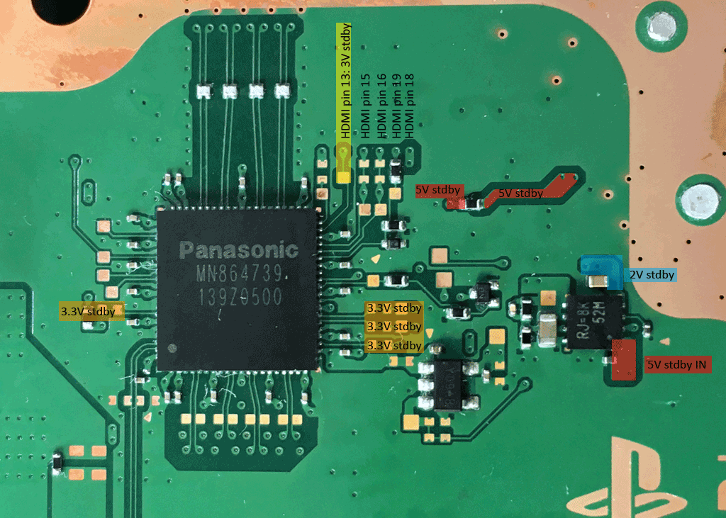
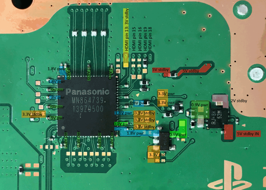
-Removed and replaced the encoder IC like, 8 times, HDMI pins finally reading mostly correct. Pin 18 has no voltage and pin 19 has no reading in diode mode. Console now boots up to white light but has no display.

***At this point, I tried booting to safe mode. When I wiggle the HDMI port and hold it in a certain spot, an image faintly shows up and I get uncontrollably excited.

-Replaced HDMI port - No more HDMI cable wiggle and cannot get an image to appear at all, even in safe mode.

***Excitement gone; sadness and rage ensues.

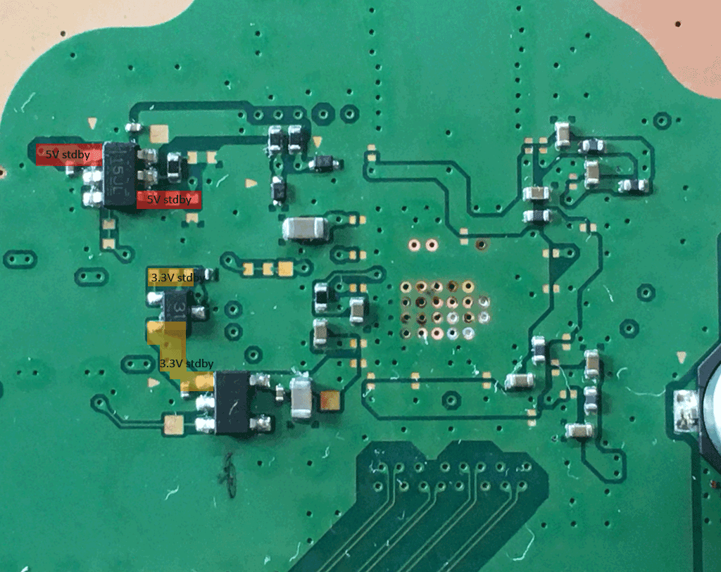
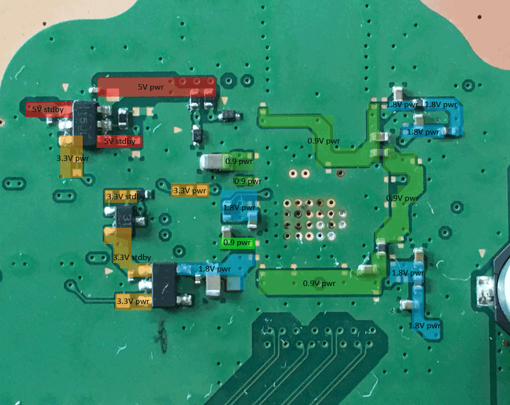
-Discovered IC7008 (15JL) power IC has the following readings with power cable plugged in and when hitting the power button:

  1. Pin 1 - 5.09v
  2. Pin 2 - GND
  3. Pin 3 - 0.0v
  4. Pin 4 - 0.0v
  5. Pin 5 - N/A
  6. Pin 6 - 4.63v

-Pulled up pin 3 (enable voltage) pin on the IC7008 IC (15JL) to test the pad beneath at power on. Reading is 0.0v.

I’ve checked all fuses on the board and all have continuity; I double checked F7001 and its fine. I can’t find any shorts on caps around the board.

What’s the next move here?!

You have come so far, so no need to be sad or enraged. Some times lightning strike damage can be an easy fix and other times a pain to find all damaged parts.

At IC7008 (TPS2553DDBVR) pin 6 is the switched output. Pin 1 (Input) and pin 4 (NOTfault) should read 5V in standby. If powered on pin 6 should have 5V.

I would lift carefully pin 6 of ic7008 and see if pins 4 and 6 have 5V when enable pin 3 is high.

If so, I think the IC7008 is fine and the next candidates for your issue are the diodes D3003, D3004, D3006 (for HDMI pin 18) and D3005 (for HDMI pin 19) and their components R3023, R3024 and C3034.

thanks for the kind words! The sad/enraged part is just part of the emotional cycle while trying to track down and fix this thang lol. Even though it’s been a struggle, I actually appreciate how much learning opportunity this console is providing me! It’s really giving me a chance to do some in-depth diagnosis and experience replacing various parts!

I’ll definitely test those other components you suggested!

Quick question though. I was under the impression that pin3 receives voltage to the switch; if I’m getting 0v to the pad with pin3 lifted, shouldn’t I track down the missing voltage there?? I’m not familiar with how these switches work and I’m still learning how to read the schematics, so pardon my ignorance!

If you press the start button and the PS5 boots, pin 3 should show 3.3V. This 3.3V enables switching the 5V input at pin1 to the output side at pin 6.

The 3.3V are not present in standby:

power on:

Small update. I still have pin3 on the 15JL pulled up but can reach the pad under to test.

All standby voltages are good, with the exception of pin4 on IC7008, where I’m getting 4.6v rather than 5.

  1. 5v Line: No 5v power, confirmed again today.
  2. 1.8v Line: Good all around. I replaced that chip about a week ago as I was getting no voltage on power. Looks good now.
  3. 3.3v Line: Here’s where the mess starts. The two bottom chips and test points are all good. The pin3 pad and test pads have no voltage.
  4. 0.9v Line: More mess. The only good tests are are C3016 and the test point. There’s no other 0.9v power anywhere.

Aside from asking “what should I do next”, for learning purposes, where does this power come from exactly? The HDMI encoder?

At IC7008 (15JL) the 3.3V enable line (PSW_HDMI_5V) comes direct from the southbridge (Pad R7).

A) Do you have a resistance or diode mode reading at the pin 3 pad or the two pads below the lifted pin 3?

B) If pin 6 is also lifted and you inject 3.3V at the lifted pin 3, does pin 6 has 5V?

The switch and dcdc converter bugs around the HDMI are generating different voltages for the HDMI circuits. They are all switched on by the southbridge by different lines.

5V_ever → IC7008 (enabled by PSW_HDMI_5V from SB) → 5V_HDMI
3.3V_SS_PG1 → IC7011 (enabled by PSW_HDMI_MAIN from SB) → 1.8V_HDMI
1.8V_HDMI → IC7012 (enabled by PSW_HDMI_MAIN from SB) → 0.9V_HDMI_SB
1.95V_ever (2V in the image) → IC7010 (enabled by HDMI_0.9V_PWRON from SB) → 0.9V_HDMI

standby:

power on: