Hello everyone
I have a problem with a switch. I got it back with a short circuit on the m92t36. So I changed it, did the tests to check that everything was fine, then plugged it in to test if it turned on well. And I couldn’t even read anything, the tester screen was barely lit.
so I rechecked around the m92t and short circuit again. I changed it again, no more short circuits, everything is fine. I put it back on and bam it jumps again. I just did it a 3rd time and the same. Does anyone have an idea of the problem. Thanks in advance.
Maybe check usb for bent pins?
hi no no short circuit on the USB I check before restarting. on the other hand when the m92 dies I have a short circuit on pin 8 of the usb as well as on some caps around the m92. But everything goes back to normal as soon as I change the m92
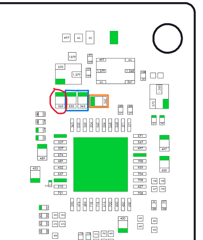
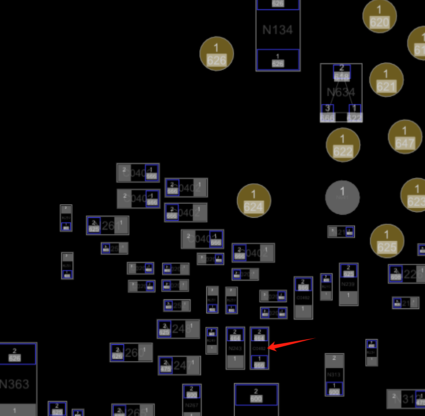
so here is what i got once my m92t blew up again and this time just trying to start with a battery. on the first image, in the blue and orange rectangle the components are short circuited and the one surrounded by red I have no reading!
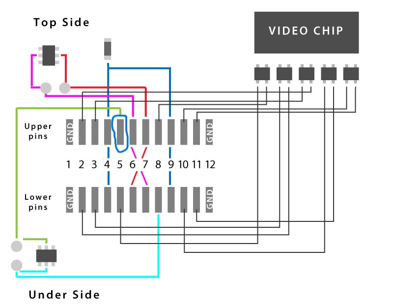
and on the second image pin number 5 circled in blue is the only one with a fault, in short circuit. All others have normal readings. Furthermore, it should be noted that on this version of the card I do not have the two components in under side and top side.
Determine what the pins in question are would be good start, why is the failure mode occuring on said lines ![]() (check the IC datasheet and / or USBC protocol to find out)
(check the IC datasheet and / or USBC protocol to find out)
Next, conclusively determine if this is an IC issue or an install issue, generally speaking it’s going to be one of those two things, either the M92 IC your using are fakes (which is common) or the install is bad, third and less likely option is there is a fault elsewhere causing this which what i mentioned above might reveal.
If you have a donor with an original M92 IC, i’d probably pull that and see if the same occurs, if it gets fried once again then you can look at the other options.
salut alors j’ai essayé avec un donneur ou un neuf c’est la meme chose donc visiblement le problème viens d’ailleurs. Ce n’est pas non plus un problème d’nstallation après l’installations je vérifie tout ce que je connais, c’est à dire en mode diode tout les principaux composant autour du m92 et l’usbc. Et je ne trouve aucun défaut. Par ailleurs je viens de changer un port uscb et un m92 sur une autre switch et tout fonctionne, donc le soucis est vraiment sur la carte avec un composant défaillant que je ne trouve pas:(
Par ailleurs j’ai lu que quelqu’un avait changé le EN ce que j’ai fait et le m92 à qd meme grillé juste en branchant la batterie et en démarrant avec le bouton.
hello so I tried with a donor or a new one it’s the same thing so obviously the problem comes from elsewhere. It is also not an installation problem after the installations I check everything I know, that is to say in diode mode all the main components around the m92 and the USBC. And I can’t find any fault. Besides, I just changed a uscb port and an m92 on another switch and everything works, so the problem is really on the card with a faulty component that I can’t find ![]()
Furthermore I read that someone had changed the EN which I did and the m92 almost even burned out just by plugging in the battery and starting with the button.
So if it isn’t option 1 or 2 then it can only be option 3 in which case you have to determine what is causing the fault, which as mentioned means identifying the lines in question and working your way back.
Also, you shouldn’t blindly change components (EN IC for example) without first determining there is even a fault with it to begin with as you just muddy the water, for all you now know the first M92 IC might have been fake or a bad install and your swap with a donor was fine but an issue you caused then triggered a faulure (just as an example) . did you reball the EN IC properly with stencils and solder paste? or use a new preballed IC? if you changed the USBC port did you check with a breakout board resistance from one pin to another (nearest neighbour) and ensure none are bridged to one another? if the USB diodes are present on your board rev did you check to ensure none are shorted out? have you checked the filters and two traces at the P13 IC and ensured there is no domage here as this is common in USB damaged scenarios and can often do this and sometimes take out the SoC in the process.
After you’ve identified the lines in question and determined what they are and where they go so you can better identify the cause of the fault, it’d also be worthwhile checking your primary rails resistance to ground (not diode mode) ones of interest would be SYS, 1V8PDR, 3V3PDR and if you have a known good donor board, compare these readings with it.
hi so I completely agree I probably shouldn’t have changed the component (with a new one so no reballing and after only 3 burnt outs) but in desperation… I read all the posts on site and even though I didn’t believe it, it turns out that it worked for at least 2 people. In terms of soldering, installing components on cards, don’t worry, it’s my job, I know what I’m doing and I do it well. I actually changed one to another switch but there, the problem came from the USBC with torn tracks, bent pins, and today it works perfectly. On the other hand, I’m not as “good” at troubleshooting when I don’t have any diagram. I therefore rely on my experience and on the experience of others who are much more seasoned than me, like you for example or many others. I try to stay as logical as possible. And I ask for help because for me it is incomprehensible. For the USBC socket I haven’t touched it, it’s impeccable. I tested it with a breakout board in diode mode and verified that there was no short circuit between each pin. Nothing That said, I think I only did the check in diode mode in one direction (red to ground and perhaps I should have done it with black to ground). So I’m going to do the tests again once the m92 is changed again. And if nothing is wrong I think I will remove the USBC just to prove to myself that the error is not coming from there. Regarding the p13 and the philters I checked everything too, but to simplify I can remove it. Normally I checked the rails in both diode mode and continuity mode and saw nothing but it’s possible I missed 1.
The reason in these cases, in all likelihood, was probably as a result of them cooking the board during M92 IC rework to the point where the EN IC which is pretty well directly on the opposing side then became dislodged and caused a short or simply open circuit ![]()
future reference regarding the EN IC, if you ever suspect it’s bad, do the following instead of swapping etc, check the resistance to ground on the primary output ie. 3V3PDR if that’s all fine then see if the output is high following prompt to boot if it is then your can safely say the IC is fine and doing it’s job, if on the otherhand you get no output then you’d then check and see if the enable line is high (ie. is it even being told to turn on it’s output) and go from there. This is pretty much the exact procedure you’d take with any other form of regulator / buck/boost converter etc ![]()
You do have a diagram in this scenario, you have the USBC protocol specification and you also have a datasheet for the M92 IC (or near as damn to it, about 95% close to it)
Regardless, you wanna get out of this habit of requiring schematics and diagrams as you have in front of you a board which combined with your meter in continuity is fundamentally a boardview, most IC’s have avaliable datasheets to supplement your findings and in the event there is no datasheet then more often then not the info can be inferred by various other means ![]()
Completely undertadn, we all standing on the shoulders of giants and were are all learning ![]() . Unfortunately in this scenario there isn’t a one size fits all solution to this problem as it could be a variety of things which is why i can’t just give you 1 trick solution but if you can look up those things i mentioned prior and measure those rails then you might be able to narrow it down or find the problem which might help me lead you to a solution, if your unsure of anything i’ve said prior search the forum for the key terms i use followed by my username for further explanations as i’ve covered a lot of this stuff before.
. Unfortunately in this scenario there isn’t a one size fits all solution to this problem as it could be a variety of things which is why i can’t just give you 1 trick solution but if you can look up those things i mentioned prior and measure those rails then you might be able to narrow it down or find the problem which might help me lead you to a solution, if your unsure of anything i’ve said prior search the forum for the key terms i use followed by my username for further explanations as i’ve covered a lot of this stuff before.
get out of the habit of using diode mode, it simply does not have the resolution and instead use resistance, for example you might have a scenario (just for example) of junk in between usb pins (again, just an example) which is causing a “high short” across pins (you want to be checking for this from one pin to the next and not just relative to ground) which you’d be able to see clearly in resistance but would probably miss in diode mode. Same goes for measuring your rails, avoid using diode mode as the values it spits out are fundamentally useless for any real form of verification outside of gross pass/fail test.
I’d save changing the M92 IC just yet, and i also wouldn’t pull the USBC either unless the tests I mentioned in my previous post come back with anything positive…
The Switch should boot without the M92 installed (albeit with an error) do you get this?
Check everything i mentioned prior before randomly removing things, rail checks i mentioned earlier would almost certainly verify is this IC was at fault in most cases.
Good luck ![]()
ok I understand what you are saying but not what is happening ![]() I control both in continuity and in diode mode it depends on what I have to control. Indeed the switch starts with a charged battery and the error is a classic error 2101-0001. But she confirms that it is the m92 which is faulty. I tested all the components around the m92 and I found nothing when comparing with another card.
I control both in continuity and in diode mode it depends on what I have to control. Indeed the switch starts with a charged battery and the error is a classic error 2101-0001. But she confirms that it is the m92 which is faulty. I tested all the components around the m92 and I found nothing when comparing with another card.
Well I looked at the card closely again and realized that the bq had probably been changed. so I removed it. I also deleted the p13 I had weird measurements on continuity filters when comparing with another card. then I put in a new m92.
And the perfect without battery the tester indicated 15 v 0 amp which is normal without bq. Then I put a new bq in, did the checks, they were good. But as soon as I powered the bim card the m92 burned out again:(.
Now my tester indicates 5v and 0.08 on the m92 side and remains black screen on the p13 side.
Frankly I must be stupid I don’t understand what can happen especially since the bq doesn’t have a short circuit.
I will therefore continue my research (I now know that I have no problems between the USBC and the M92) and read your posts hoping to find something, even if I sometimes do not understand all the terms you use.
I’m also experiencing this problem and I’m not sure if we’re experiencing the same problem. First of all the switch is bootable, 5V charging is fine, 15V will burn the M92T36. and I found it strange that without battery the 5V power supply will start the 3.3V rails, by comparing for a normal motherboard I think it should be abnormal. And the diode for the 1.8V rail in the M92T36 is 2
00v, normal motherboards are 330v. i’m sure the ENxx ic is normal, he’s all capable of outputting 3.3v.
And I removed the enxx ic and the problem is still there, so it has nothing to do with the enxx ic!
Good morning
I agree the ENXX has nothing to do with the problem. I changed it (without conviction) because someone had done it in a post and it worked for them. I didn’t have time to look again. As I can’t find a “bad measurement” I’m going to change the mosfets one by one. For this I will use a donor board which works but with a black screen. I will put a mosfet on the donor and I will check if it works and so on. I will eventually find the component(s) that have a problem.
Well I’ll come back after more tests ![]() As I said and read in another post I changed one by one the mosfets and other components around the m92 with a card that boots and all the components work normally! then I did another test and I came across a fault at pin 18 (18V). On the m92 side I only have 180 ohms instead of 2.2 k on a good card. So now I have to find where it comes from, I admit that for the moment I haven’t found it. If anyone has a clue to follow the 1.8v I’m interested, but it seems that it is wandering all over the map…
As I said and read in another post I changed one by one the mosfets and other components around the m92 with a card that boots and all the components work normally! then I did another test and I came across a fault at pin 18 (18V). On the m92 side I only have 180 ohms instead of 2.2 k on a good card. So now I have to find where it comes from, I admit that for the moment I haven’t found it. If anyone has a clue to follow the 1.8v I’m interested, but it seems that it is wandering all over the map…
thanks in advance
Then I think we are experiencing the same problem, this pin resistor is 200 ohms. I removed all the 1.8v locations on the motherboard and determined that the cpu was causing it. But I own an oled motherboard that is also 200 ohms and it works perfectly fine, because this motherboard was shipped in June of this year and it was shipped with this resistance. So I think this pin may be perfectly normal, although his values are very wrong, but it should not affect m92t36