M92T36 replaced still short on VCONN_IN

Now I m total confused…

I reassamble the Switch and powered it on. It started but it freezed on the mainscreen and both working tested Joy-Cons would not connect to the Switch neither plugged nor wireless. At the second try it recognized the left Joy-Con plugged-in for a short time than it lost connection, while I was unpluging and pluging the right Joy-Con. I a third try it freezed again.

I checked the mentioned cap above the M92T36 again and now it shows a reading…

Calvin i saw a youtube video yesterday and a guy had the same problem with the freeze/no power with both joy con attached…
The problem was that there was a small amout of corrosion and dirt on one of the joy con flex cables

Thank You, Dallas. It was a good hint. I found corrosion at two pins at the right Joy-Con rail. After cleaning both rails both Joy-Cons are working plugged and wireless. Only the ‘Plugging’-Animation for the right one is missing.

Nice!

Im glad that it worked :slight_smile:

I still get no snap animation, if I plug or unplug the right Joy-Con.

I tried the right Joy-Con on an other Switch and the animation shows up. So the Joy-Con should be ok. I tested an other working right Joy-Con and also got no snap animation. I first clean the contacts and second changed the connector in the rail, but no difference.

Does anyone knows which pin is in use to recognize the pluging of the right Joy-Con?

Pins 1&2 are ground, then comes jdet which is high when the joycon is connected over bluetooth and low when it isn’t and then 5v powersupply

check that you have 5v on the 4th pin

I meassured the connector pins right and left:

Values: Joy-Con connected/unconnected
Right Joy-Con

Left Joy-Con

It seems that on the right side a switching is missing.

I tested an other Switch:
How it should be:

Have you checked the protection diode (marking “PU” on the underside, near to the led)
It can also cause this issue
There is another one near it so you have a reference

I checked on the backside the “PU” and “MX” / “ZBL” ics of both Joy-Con ribbon cable connectors and compare it to a fine working Switch. I can t find any difference in continuity and diode mode meassurements. And I have no idea for checking this parts while the Switches are assembled.

I checked the voltages at the connectors again on both Switches and found, that the 5V on the left side are missing if the right Joy-Con is connected…

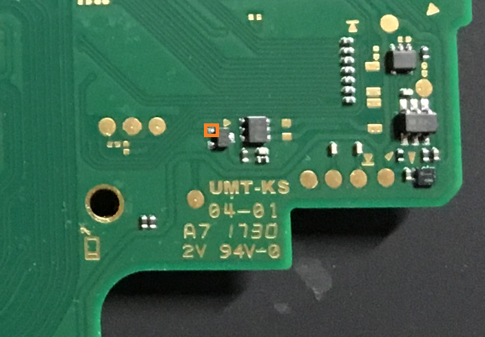
Does anyone knows where this line goes to? I checked both sides, but I can t find the other end.

Where do you guys get these data sheets from?

Master Calvin makes them, and he is a real hero that share this information for free.

straight up! that is awesome!

Maybe to joycon charge gpio on the soc?
Would be my guess

switchbrew:org/wiki/Bus_services#GpioPadName

I hope it is not a problem with a CPU pin. :stuck_out_tongue:

Is the Tegra soc unique or interchangeable with a Tegra soc from a donor board?

You need to swap soc & emmc because soc has (unique) keys for the data on the emmc and emmc has (unique) data for the soc, rest should be no issue

It seems to be a problem with the soc. I disoldered the soc from a donor board and found the corresponding pad under it… so the false switched enable signal for charging the right Joy-Con comes direct from the Tegra X1…
and my skills are not good enough for changing a soc. :frowning_face:

Have you tried using a resistor to force the signal to be high/low?
Could be a workaround but i don’t expect the charging symbol to appear in the controller menu