the SoC is marked ODNX02-A2, the owner said that the switch only problem was charging, after replacing the M92 i used a 5V 2A USB phone charger to test/charge the Battery, the battery was 3.2V i kept it charging untill it reached 3.8V, still no boot, the switch takes arround 200mA when i press power button, let me know if the Cap you 're refering to is the same i’m suspecting, for my case it’s the only cap that seems shorted, thanks in advance
yeah that cap tests almost as a dead short on erista and it’s normal, no idea what it is…maybe some sort of int/ext current sense 
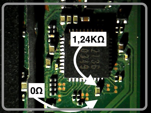
@Ganoninc The cap measures approx 1K/1.3k depending on probe polarity on my mariko board, possibly indicating another issue on yours, though it maybe the other faults are affecting your measurments, I haven’t yet traced this line out to see what/where it is and what it’s doing.
@Spets Can you confirm if the console ever booted stock HOS prior or after M9 IC replacement with a known good battery?
If so prime candidate would be BQ IC, if it’s unpatched i would boot hekate and post images of the console info sub categories with battery and cable connected, which may offer possible confirmation
Actually, my multimeter acted like it was not certain of the reading on this one. For instance, right now I get 602Ω but if I keep measuring it’s getting lower and lower. I can see the resistance fading more or less 1Ω each 5 seconds.
Regarding the SX Core, I cleaned the flex cable again and I’ve seen no short. I’ve also updated the firmware of the chip using the mini-USB IO.
On top of that I’m still learning how to solder and I’m staring to think that I failed my original attempt of installing the mod chip because I bought a cheap soldering iron. Two of my pans are already burned and the solder doesn’t stuck on them. I have to understand why it happens so fast whereas I clean them quite often. I can’t even remove a 0.8 mm cap on my broken GPU so me doing it on the Switch won’t happen so soon.
Would recommend getting a KSGER branded T12 soldering station as they’re low cost but decent performance, opt for the metal housing and aluminium handle variant (the plastic handle ver has poor strain relief and I’ve had to repair the wires multiple times) I’d remove the annoying safety/standby switch inside the handle either way though
You can also pick up a knockoff hakko iron tip temp calibrator so you can save accurate temp profiles on the station for each tip variant.
Avoid conical tips, while some will say “they’re a good all rounder” i would say they’re not good at any one thing and are poor in almost all instances/applications. My goto is a D24 “chisel” tip, which is what I’d use in your case to remove these caps at about 420c (calibrated)
Next goto tip is a JL02 which is great for tinning pads (connector pads etc) as it’s great at releasing the solder.
As for flux, chip quick is decent, though I’ve had no issues with my suspected knockoff amtech or kingbo flux which works fine.
That’s good and indicates the modchip is likely fine, I’d put it to one side for the time being
Bear with me I’lo find specifically what this line is on latet
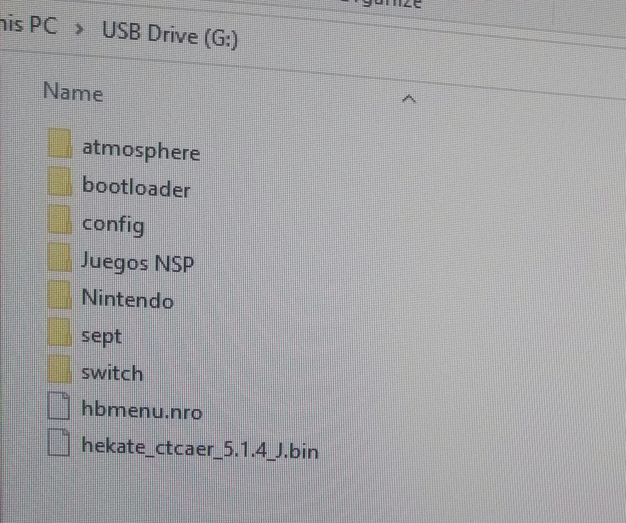
I have no idea how N Switch hacking is, but there is A 64gb microSD card on it that has the files on the image, i don’t know if i’ll need some special manoeuvre to get it to boot, i did check all Voltage seems present, the SoC got its 1v to
Is the Switch the new version or the old one?
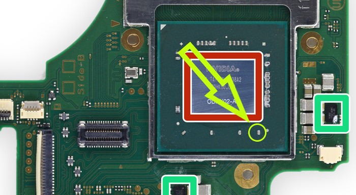
ODNX02-A2 SoC, stated as erista
If the sd card belongs to the Switch you can try to start the cfw from the sd card.
- copy the file “hekate_ctcaer…bin” to your pc
- download and install TegraRCMGui
- start TegraRCMGui and plug the Switch to the pc. The pc should recognize the Switch as usb device
- shut the Switch completely off
- insert a jig in the right JoyCon rail. I made mine from a paperclip. It should only bridge pin 1 and 10 together
- Hold “Volume +” and than press “Power”. The Switch screen should stays black and should apears at TegraRCMGui
- In TegraRCMGui brows to the bin file and inject it as payload
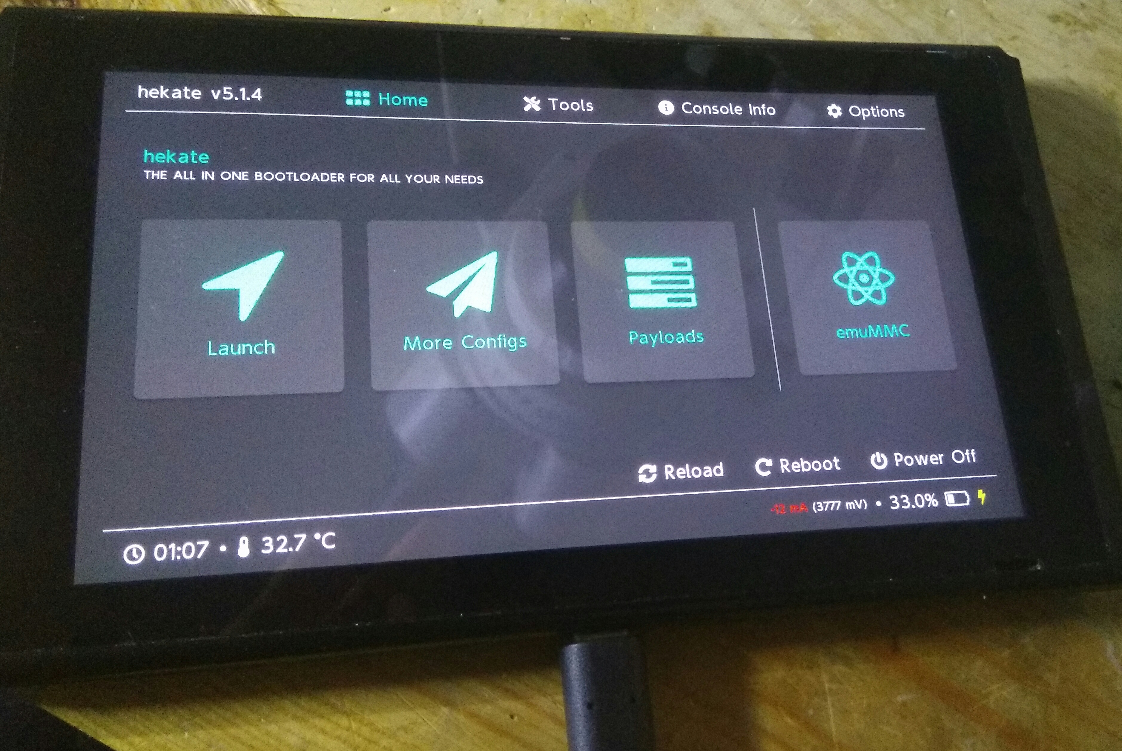
- If Hekate is started. Go to “Launch” and try “EmuNAND CFW”
Thank you guys for your help, i followed the steps and now it’s booting and working, and charging… So my part of the fix was done correctly , it was a soft problem
Also that short on the Cap upper side of the SoC was normal
Hello,
I eventually ordered and received a T12 with a D24. I must say it works way better than my previous soldering iron. So I managed to remove the 3 caps and took my multimeter to get some readings.
Here they are:
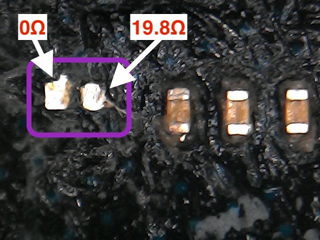
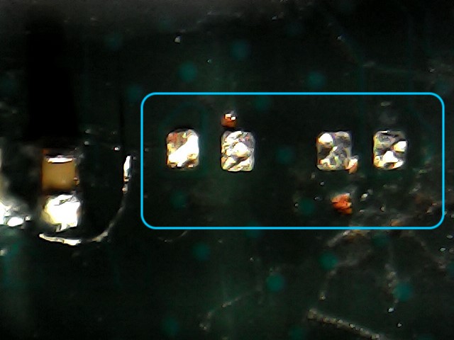
On the left (SP1)
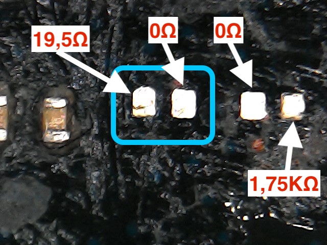
On the right (SP2 + looking burned cap)
I don’t know if this is good or not but I notice that those readings are close to the ones I had when everything was working fine, prior to the sad night when I left it on the dock downloading a game.
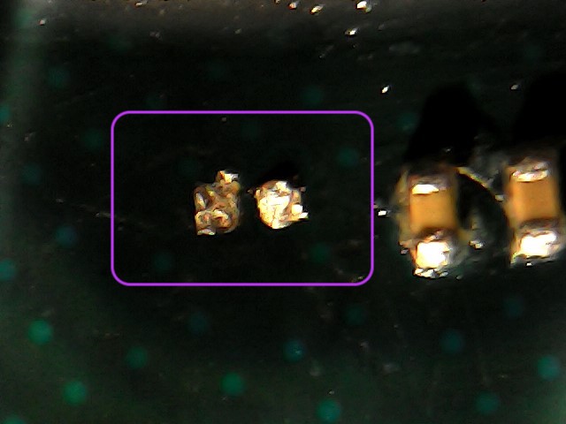
None of the removed caps survived the removing process. If I remember correctly I read a long time ago it was possible to install the SX Core without these caps. Could it be what’s next?
I also thought maybe I could place the suspected corrupted NAND into my working Nintendo Switch and use hekate to restore the backup of the Mariko unit made by the SX Core. Some people say Hekate doesn’t use the keys of the CPU to restore/backup the NAND, it just copies bits. If it’s true, the writing could be possible. That would be way easier than installing the SX Core again in my Mariko unit.
Shall we try that?
Hi there,
Your 1VX rail looks good (19ohm)
But unfortunately your 1V8PDR (1.75k) doesn’t look right (still) was putting it down to a probing issue. But i hadn’t confirmed the normal reading on Mariko until now.
Can you disconnect batter & power, then disconnect the EMMC module, put your meter in the 20K position and check it at the following location instead, both probe polarities (relative to ground)
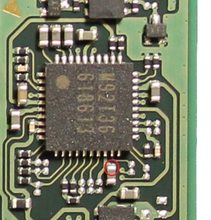
Should be approx 10k - this tends to bounce around a bit more on mariko boards which is normal.
If the reading remains 1.75K then unfortunately it’s not looking good, there are a few more bypass caps on the SoC on this Rail, but unlike the previous one which was removed they should have oriiginally been nowhere near your soldering iron at the beginning and as such are unlikely to be damaged.
Give the pads a really good scrub, and a really good inspection, sometimes the heat from a previously shorted cap can put a carbon layer between the two pads causing these low readings
Thank you for this quick qualitative reply.
First I did clean again the pads with a toothbrush and some IPA and checked the resistance again and it’s still around 1.75k.
Here are some pictures of the pads (with a voluntary indirect light to highlight some scratches)
On the left (SP1)
On the right (SP2 + looking burned cap)
Now for the readings you asked, it’s unfortunately far from the 10k as my multimeter reported 1,87K
Here are the detailed results:
I used the USB port as ground point and I checked the resistance using the black probe on it first and then I switched to the red one
Using the black probe on ground point:
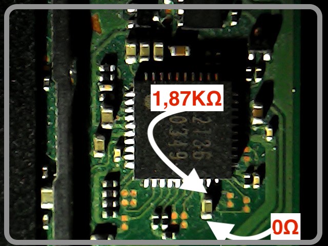
Using the red probe on ground point: