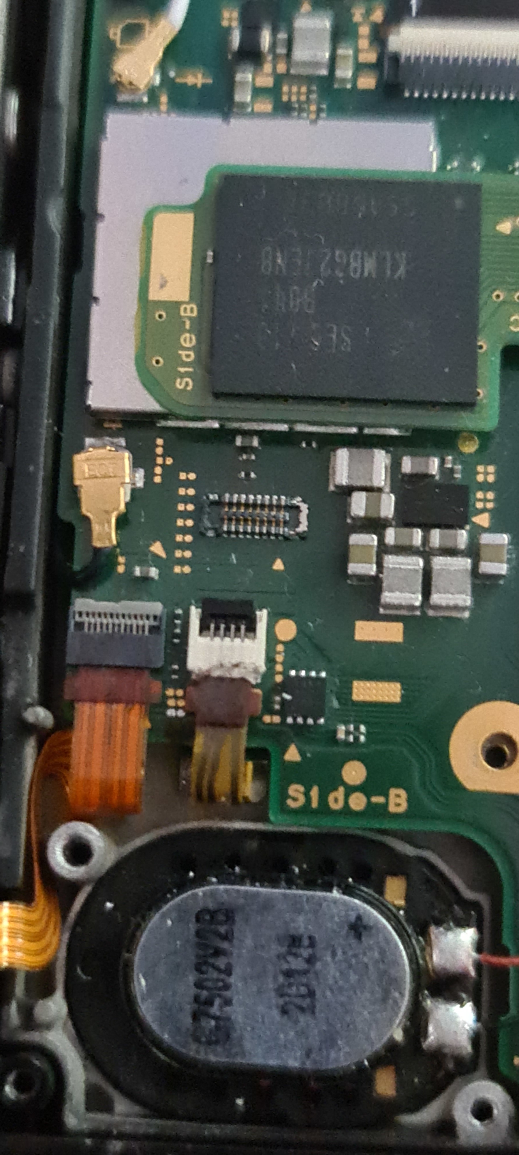
I have buyed a faulty switch (Old no Mariko) that stock in RCM. It cant read a Boot.dat. The Micro SD Card slot wont be reding out (i have Test 2 New SD Card Slots nothing help)
on the Pins there are 3.3V or 1.6V on the blue is 0V. but on the testpad on the Mainboard are the blue with 1.6V
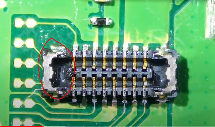
Worth noting that if all the pins on the board connector look good and test fine in continuity then the same tests should be done to the opposing connector on SD flex side.
Those SD flex boards are very fragile and commonly break, because of the bend on the flex, test continuity from the connector all the way up to the micro SD pins, if you find the break, scratch back the polymer coating and solder a wire accross .
I suspect the OP has a different issue, i get the impression his console doesn’t even boot.
Thank you again for the reply. I have used two sd card readers and neither of them seem to work. However it did work for a minute yesterday. It sounded like a bad connection problem, so that’s why I checked the continuity. I tested again with SD connector attached and it seems to be there is another pin which is disconnected from the pad. *Why didn’t I just replace the whole connector… *
You can see it from this video. youtu . be/8Ia6qASINsA
P.S. I’m gonna make a compilation of all these repair attempts if I get it to work
Ah yeah, definitely at least a couple of those pins aren’t connected at the base of the pads.
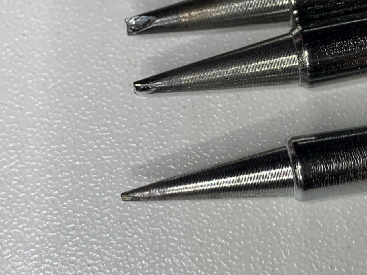
While some will not reccommend this, I will in this case. If you have an old conical style tip, or if you threw one in the bin earlier then you can pull it out, and take it to a bit of sand paper and fashion it into a (T12) BCM2 style tip, i find this shape particulary good at tight connectors and because of the large tip area it has enough thermal mass to give a good joint, I’d typically use this style if i have to resolder a pin on the LCD connector for example as my usal goto D24 is of such a shape that it can’t properly transfer the heat in these cases.
I mean it won’t be as good as a store bought tip and it will lose whatever coating was originally present but it should do the job… and lets face it, there’s no other good use for conicial tips
I think it’s a good skill to learn, and you’ll appreciate it later on down the line, especially when you don’t have any of those entire connectors in stock
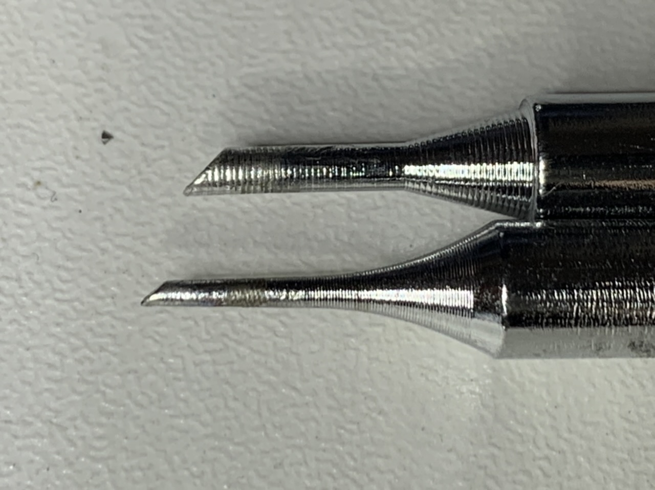
Yeah, those beveled tips in your first pic would probably be a good choice, though, i see what you mean about the quality… the manufacturer was definately using a blunt turning tool that day.
I’d be using leaded solder and a temp of 420C, it might also be worthwhile verifying the tip temperature by placing the tip with a blob of solder on the end onto a k-type thermocouple and ensure your getting something that’s atleast similar temp wise to the setting set on the station, as i imagine the thermal transfer between the interfaces being quite poor with the quality of the machining on these tips.