Missing pad in southbridge

Hi guys!

So I have a one beep not light PS5 Slim EDM-040 console with a HDMI port bad and after reading standby voltages I had 1.2V, 3.3V, 5V, 12V then I checked the power supply and it didn’t get me the 0.300-0.200 mAmps when I was trying to turn it on so I decided to take the southbridge off.

As you can see in the photo is a Cxd90069gg, I started with hot air at 200*C worming up the surroundings, then I was gradually adding more heat every 2 to 4 minutes till I stop at 400*C and adding more flux from 300*C. When I saw the bubbles around the chip I knew that I was closer to extracting the chip, I didn’t pull it straight away I just push gentle in a corner of the chip and when I saw that it moved I lift it up with my tweezers.

Now, the problem is that after I lifted the chip I realized there was a pad that came off with the BGA chip leaving the board without that pad, I could trace and repair the pad but I don’t know if it is necessary, I got the schematics of a EDM-010 and I know that they may have a different southbridge (I’m assuming). So I came here to ask for some assistance or schematic for the Cxd90069gg chip.

Thanks in advance! And I’m sorry if left something behind you can ask me anything, I’ll be glad to answer

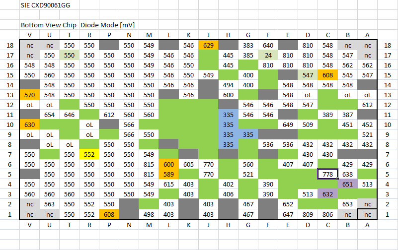
Note: in the schematics that I found of the EDM-010 it says that this is a NC (not connected) pad, so I don’t know if I am lucky enough to leave it as it is right now.

Also, there is this psdevwiki that tells me that the A2 pad is NC. But this is not the Cxd90069gg chip

Wrong temperature. You need at least 420°C with 50% airflow. Post a photo of the pads.

Thanks for your answer @Repairman, I’ll keep that in mind next time I do this :slight_smile:

I tried to upload photos but I keep getting an error saying “An error occurred: Sorry, you can’t embed media items in a post.”

Do I have to upload the image in other web and send you the link? I’m sorry to ask, I’m new here

upload to an external service and share the link

Thanks again @Repairman I uploaded these photos, let me know if you can see them:

https:/ /ibb. co/ 8LzxZ5vF

https:/ /ibb. co/ 23cCV3KK

https:/ /ibb. co/ n8P7TpvB

I tried to put the links here but it says “You cannot share links” or something like that. I’m sorry for this, I uploaded them in imgbb

the ones there are zoomed out, it’s just to let you a better reference point in the angle of the one that is closer and you can see the right position to identify the pad.

I must add, that before I did this, I tried the uart and I didn’t get any readings, looking forward for your reply and try to see if I can install the new southbridge :slight_smile: can you recommend flow and temperature @Repairman ?

Also, can anyone share with me please, the diode reading for the southbridge on the board? Now that I have removed the chip it would be nice to check the readings with other one that works. Thank you in advance!! :smiley:

In each corner the three pads are n.c.
The pads have beside 4C (61GG GND/69GG 3.3V) the same layout.