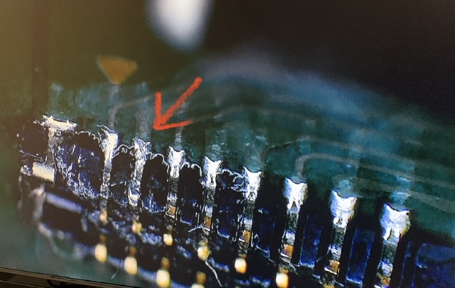
I have this issue as well. I am missing the 2 pins in the upper left positions.
I found a diagram on the forum, but I am not sure its accurate. I can not post links or images for some reason.
If it is, can I just take 2 of the ground pins and try to move and resolder them? Shipping for 2x connectors is about 2 months from China, and I do not have a hot air station.
Assuming your looking at the board right way up and the upper row, the first pin is = SD switched ground and is needed for detect, the second i believe is DAT0.
Both are necessary for SD functionality
Again, you can steal a couple of the ground pins (check with your meter) and move them over but it’s highly recommended that you replace them at a later date… while some maybe redundent i have no way of knowing for sure what the technical specifications of the connector or SD flex are, while unlikely it’s possible it requires all of them for current handling, regardless, you want them all present for stabilty at the least so consider it temporary.
Practice on a scrap macbook board connector pin or something first, as while this repair isn’t difficult it can be fiddly particularly if you don’t have a microscope…last thing you wanna do is lose another pin or make the connector worse
Yeah, if we call pin one the first pin on the upper row and count sequentially, then pin 12 and 13 would be ground.
I’ve since taken a closer look at this connector and how it’s arranged. on the pins It goes data/IO then ground, data/IO then ground etc etc this is a common and cheap technique by designers to prevent crosstalk/noise, this is common on high speed data lines to prevent a high rate of R/W errors. Just another reason to repopulate those missing pins at a later date.
Anyway glad you got your SD back up and running again orntar
I tried and failed… i might make a video compilation of my tries. For some reason the sd card connector (male?) grabs one of the pins all the time. I guess I’m gonna replace the whole motherboard connector next time
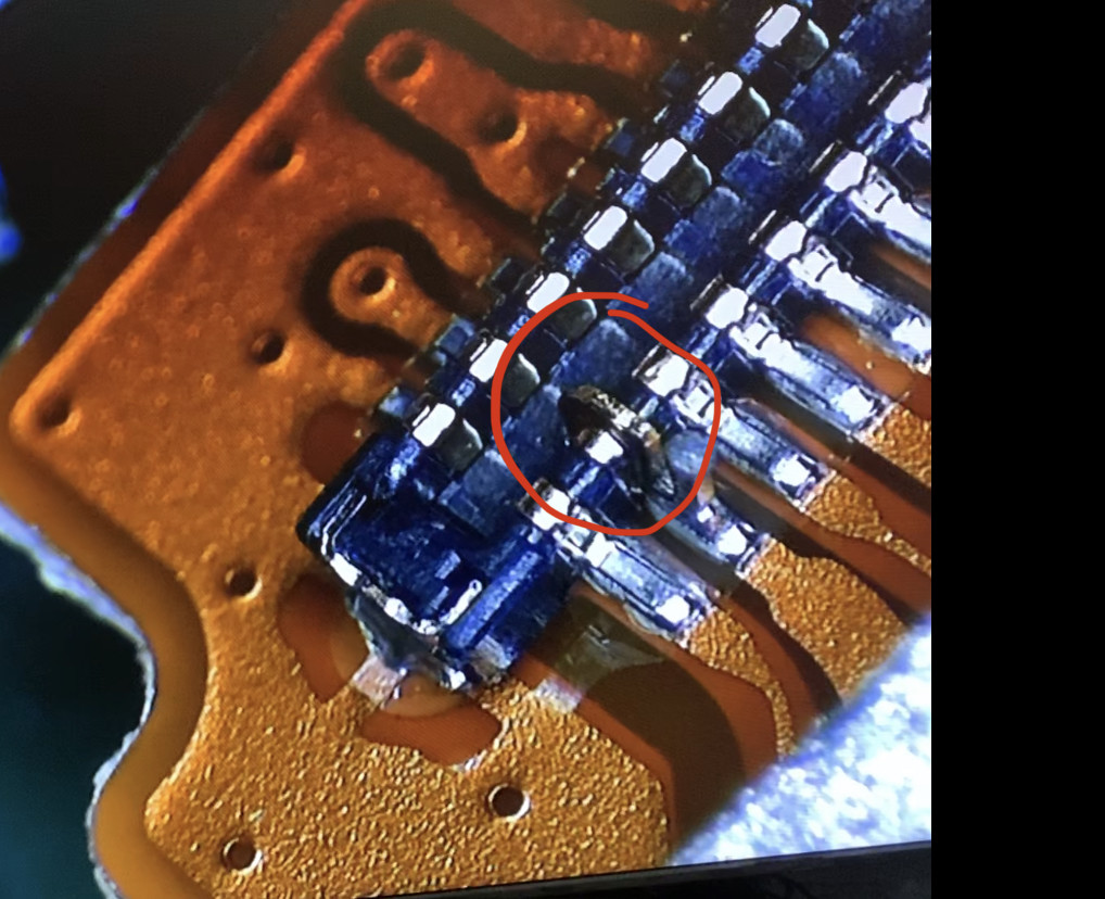
This is hard for me to tell without doing a physical inspection but it would seem as though your joint on the SD pin is not holding up, I don’t know what style of of soldering tip your using but if it’s conical… toss it in the bin they’re all but useless IMO
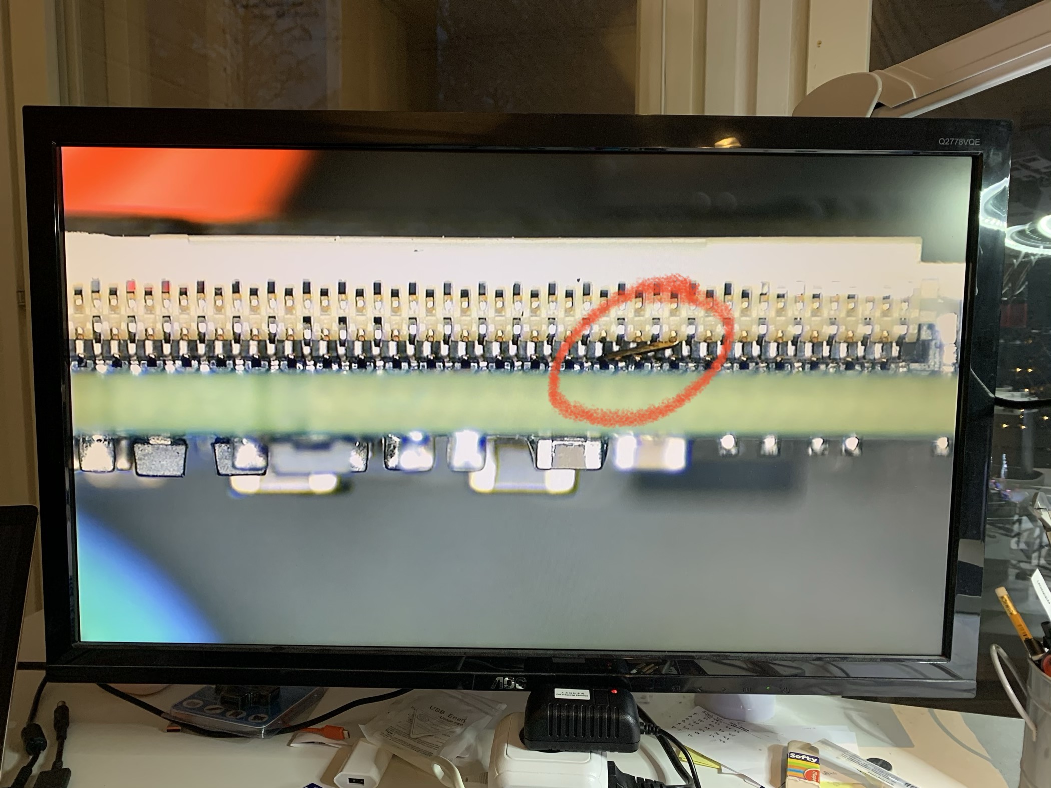
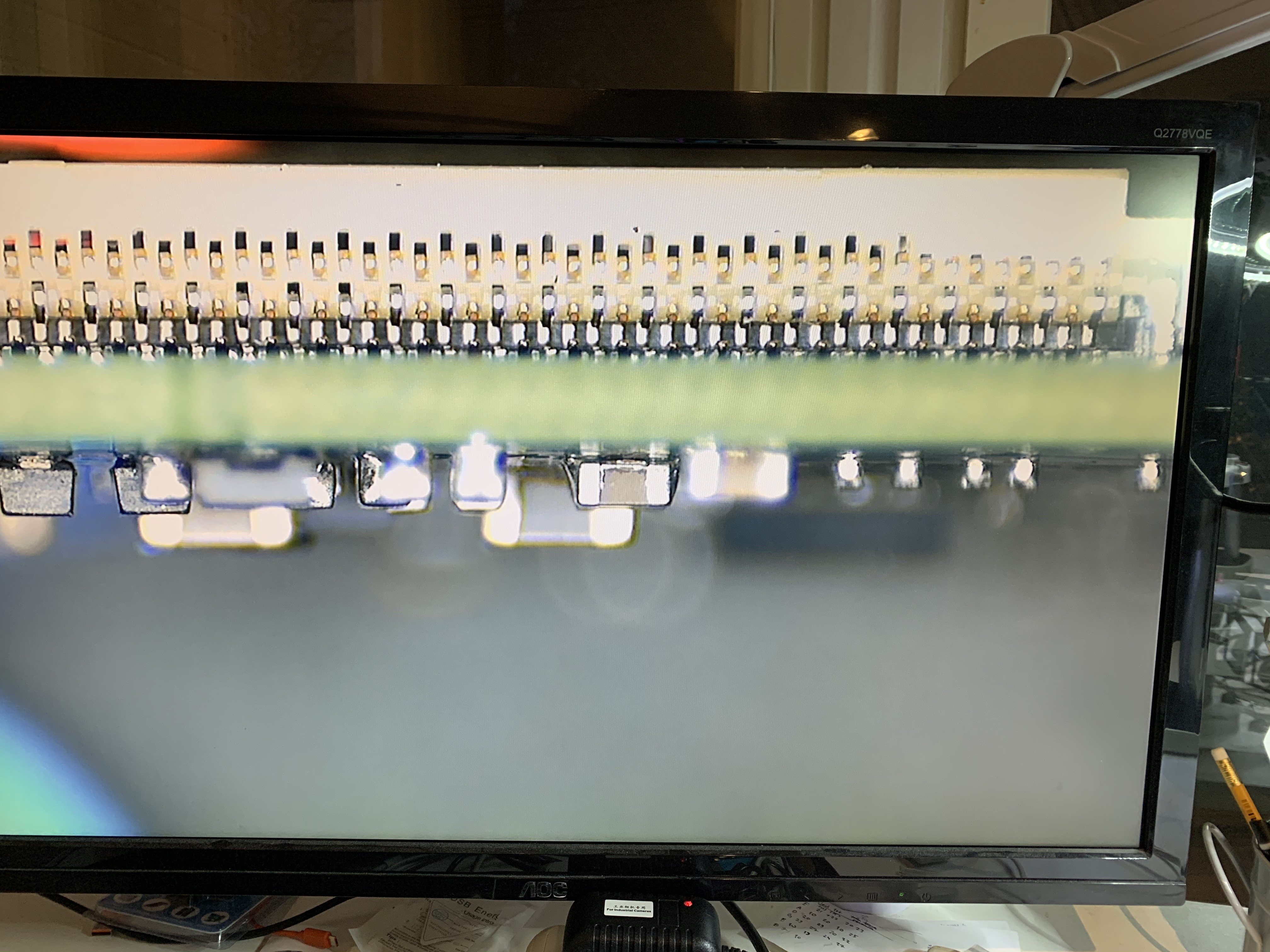
Well done with the LCD bent pin, it’s a challenge straightening them out and more often then not i find it’s quicker and easier to just replace the connector entirely, but well played
The LCD pin fix was actually quite easy. I should’ve recorded it.
Yes, you are correct about the SD joint. There is something wrong with the joint and I am suspecting the iron tip doesn’t meet the pin leg and pad. I’m using some not-so-quality tips, most of them are chisel type. Sometimes I have problem to get the solder to move to the tip. I’ve ordered A curved ”Mechanic 900M” tip. Which tip would you recommend?
It would’ve been much easier just to change the SD connector, but I wanted to try something new (and micro-sized).
Here is a picture of the joint. The PCB is on top.
hmm I’d also recommend a chisel tip (T12-D24) but maybe your particular chisel tip isn’t making great contact.
In the past in similar circumstances I’ve used a micro pointed tip and flux to begin with… which creates a terrible joint but then after come in with the higher mass tip to finalize and create a good joint after.
Btw would love to see your videos on the subject of board repair, you appear to apply logic based on intuition and advice… which is more than can be said for others
You might find if you scratch back the mask on that pins corresponding trace and then flux and tin the trace (directly in front of the pins pad - so they connect) it will more easily allow you to get better thermal transer with your iron and more easily get the solder in there.
And btw, loooking at images of the tip Mechanic 900M online and i would imagine you would struggle with this tip, due to the lack of thermal mass
I’m not very experienced with micro soldering. I’m using a Hakko 936/907 so I cannot use those long tips as far as i know. I’m gonna try your ideas next. So, first micro tip with flux then larger tip and maybe scratching a bit of mask on the trace.
Thank you for your kind words. That inspires me to create some simple videos of Switch repairs. There are lot of similar videos in youtube but perhaps I can make it somehow different. I have created few videos about electric bikes (link is in the profile).
No unfortunately, you’d have to buy a T12 handle and rewire the connector, which I’ve done before on a very similar soldering iron/station compared to yours (CSI 2901)
Yeah, Idea being your just using the smaller lower mass tip to get some solder in there and then finalizing with a larger tip, don’t hold back on the flux.
You could also tin the base of the pin before slotting it into the connector, but be careful not to accidentally tin the entire thing, otherwise you’ll have an even harder time trying to push the connector in afterwards.
Out of interest what type of solder are you using and what sort of temps is your iron set to?
Wondering if anyone has a good source for these FPC connectors. I need to replace the one on the motherboard, and don’t want to wait 3 months for it to get here from China…Thanks!
I very rarely order these connectors from China or other as I typically just replace missing pins on an individual basis (as mentioned above) As such I haven’t went to the effort to find out specifically what this connector is.
But if you would like to, then simply get approx measurments with a digital caliper, measure the width, length, height, then count the total number of pins roughly calculate the pin pitch based on these measurments, then head over to Molex site or one of the many online distibutors with a parametric search (Mouser, digeykey, Element 14 etc) FPC connectors > and input you measurments etc and see if you can find a match.
 they’re all but useless IMO