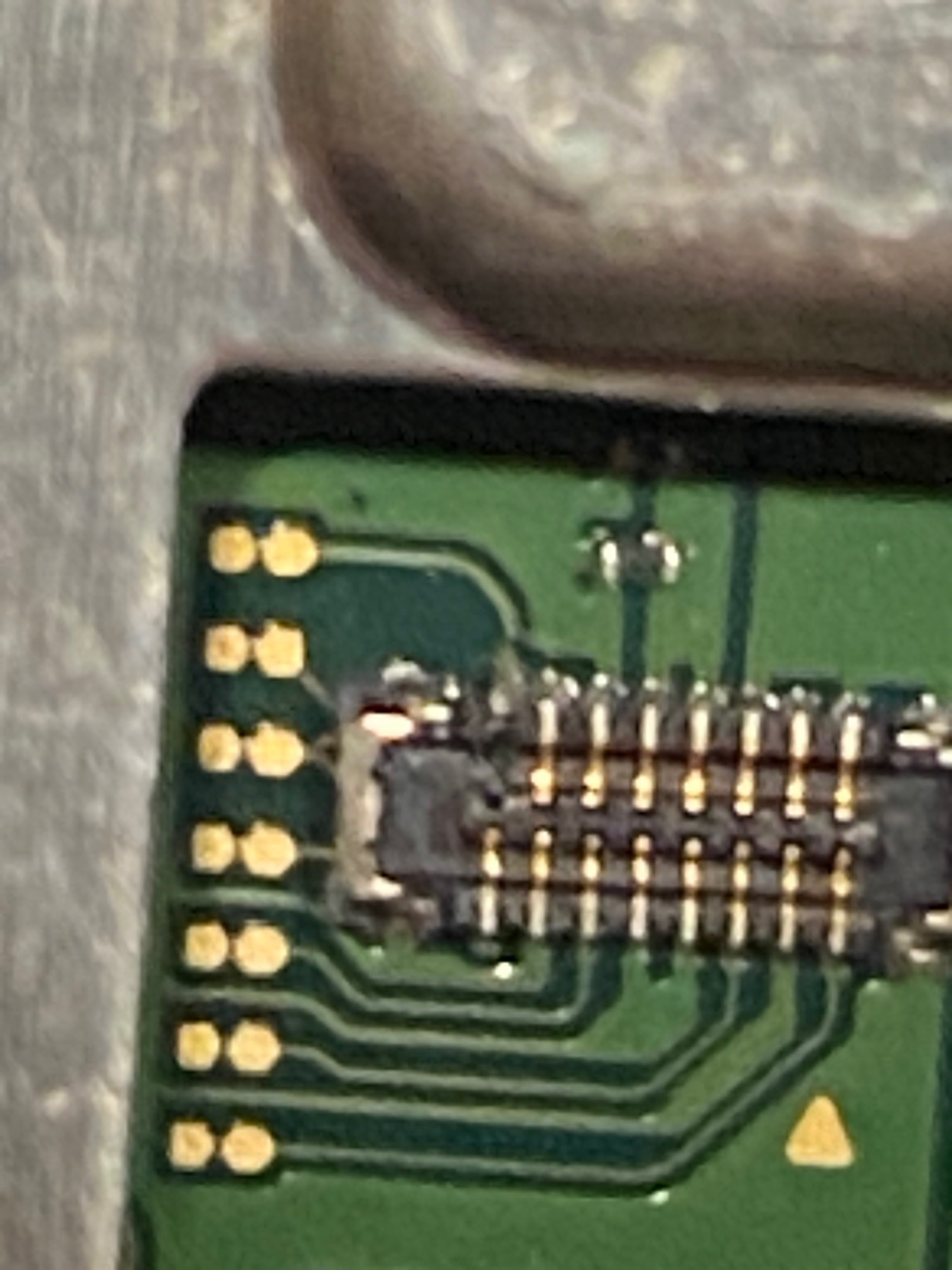
While replacing my SD card reader, I noticed that one of the pins on the socket was missing. Does anyone have any repair suggestions?
Everything else on the console works 100%
While replacing my SD card reader, I noticed that one of the pins on the socket was missing. Does anyone have any repair suggestions?
Everything else on the console works 100%
Thank you, I will give this a try
If you still have the pin you can always just solder it back on.
Replace the 16 pin FPC connector? $7 on eBay.
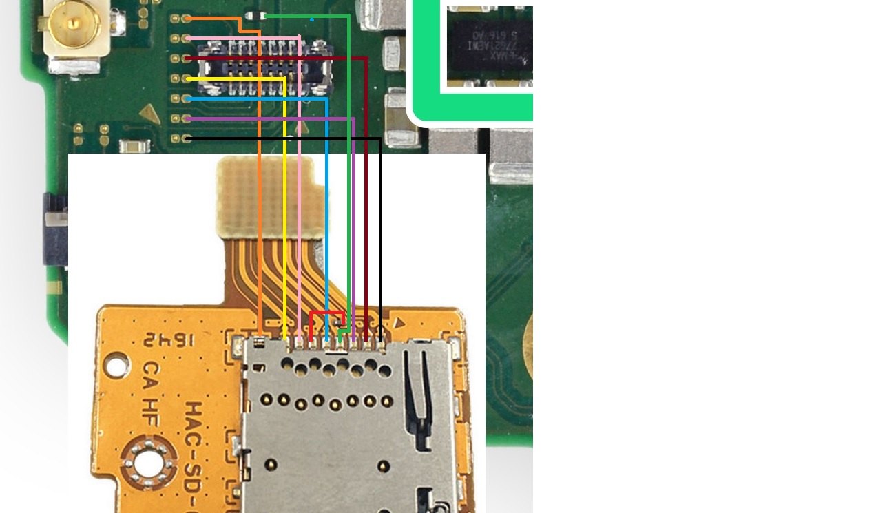
I guess you can try to bridge the one wire by soldering directly as in the picture.
I would replace the connector. Otherwise it may become a mess.
I know this is old, but I have the exact same problem, so thought I’d continue here rather than start a similar thread.
@CaptSpeirs and @DJFixiT : I have ordered the replacement connector from eBay. What is the process of replacing the broken connector?
I’m fairly good at soldering on a small scale, but I’m wondering, based on your experience, when I remove the broken one by desoldering it, does it leave behind easily usable pads that I can solder these new connector to?
Will it be fairly simple with some flux?
Thank you! This is the only faulty component keeping my kids from being able to play the switch (and keeping me from playing, too) And they’re home all day with remote learning, so you can imagine the need for some entertainment. 
Its quite easy if you have some skill
Remove the broken connector with hot air (360-400°c) / soldering iron, then apply some flux and go over it with some solder wick
After that apply flux, hold the connector with tweezers where you want it and use a soldering iron to solder the metal “frame” left & right, then the signal pins
When I did mine, I used hot air from underneath with flux to remove the old one. Then I took my iron and wick and removed all the old solder and replaced it with leaded solder which requires less heat to melt than the old silver solder. I then tinned the new FPC with leaded solder and placed it near by. I then preheated the board to about 100 degrees Celsius followed by using my hot air at 450 degrees Celsius from underneath until the solder on the pads began to get shinny, always using lotsa flux. When the pads were ready I placed the FPC on the board with continued hot air pressing down lightly for a second or two, don’t melt the new connector (always buy two new connectors in case you do). I then looked at the connections under my microscope to verify there were no shorts or open connections. Then I used my multimeter to verify continuity.
Wow. Very thorough. I should have ordered two connectors…
Is there a model of hot air gun with variable temp that you’d recommend? I only have soldering iron that can dial from 200°C to 500°C and my hot air is a cheap one that simply has “High” and “Low” settings.
As for the solder, I always remove the lead-free and use lead/tin solder. SO much easier to work with!
Thanks for the tips, guys! If you’re applying heat to the back while you’re using tweezers etc, I’m assuming you’re using an actual IC soldering/reflow station of some kind… wish I had one of those.
So after going removing the old connector and going over the area with solder wick (is this the same as desoldering braid?) there will be obvious pads to solder the new connectors contacts to? I’ve never desoldered and replaced a data type connector like this before, so just checking. The only replacement of any connector I’ve done is replacing micro usb or usb-c connectors on some android tablets.
Thanks!
A soldering iron will not help you.
You’ll need:
Solder
Heat Gun - adjustable temp recommend
Flux
Tweezers
Solder wick
Use flux on the socket outer legs
Heat it and pull off with tweezers
You can clean the pads with a solder wick
Either try to place the new one on and hit it with a small amount of solder or use solder first and heat to put the new one on.
You can try youtube or Google for more detail. Good luck.
And may the force be with you 
Thanks everyone ! Waiting on a better heat gun, and some desoldering wick, as I’ve misplaced mine, and I’ll get started on this. Will update with my results.
I will use this thread since I have the same problem.
I had to open my own switch to check some diode values. After putting everything back together I noticed the console won’t read SD cards. I opened the back plate and noticed that the SD card reader FPC-connector seemed to miss one pin.
What is the best practice to remove the sd card connector from FPC, so it won’t detach the pins? I am usually very careful when removing it and this is first time it happened to me. Is this common problem?
Hi there,
There isn’t really any special procedure to remove the sd flex, just remove the screw and grab the larger SD shield section and pull up.
The damage/pins pulled is typically caused on connection entry and later only revealed on disconnection. (due to it being blind entry etc)
You don’t have to remove and replace this entire connector to repair it, you can steal a pin from a donor board (or from a new connector)
To remove the pin from an existing board you just add flux to the pin you want, tin with leaded and gently lift up on the pin with tweezers while touching pad with iron, and transplant it onto your board with the missing pin, following the directions in reverse.
You might take a close look at the connector on the SD flex side, chances are high you will find the missing pin stuck in there…careful, it will want to ping across the room ![]()
Also, sure it goes without saying but disconnect battery/power throughout
Thanks for the reply Severence. I probably saw the pin tangled with the other pins but when I took the magnifying glass it was already gone. Must have flewn across the room.
I already ordered couple new connectors, but I was wondering maybe I can take one of the pins from that screwed up connector. The SD card uses only 8 pins so there must be some pins which are not used. How about the pin opposite the lost pin… Or maybe I can just flip the connector 180 degrees. What do you think?
Hmm, in theory you could steal one of the pins going to ground and move it over (i believe theres multiple ground pins on this connector) and while this will work i would reccommend when your new connectors arrive to then steal the pin off one of them and re-populate the now missing ground pin.
Forgot to mention, check around the speakers, the pins are slightly magnetic from memory so you might find it stuck there and maybe have a good scan around the enclosure and board… give it a good shake, last thing you’d want is that pin floating about after the repair and screwing the back on ![]()
That’s what I’m afraid. I hope the pin is somewhere else than behind the motherboard. Speakers are clear.
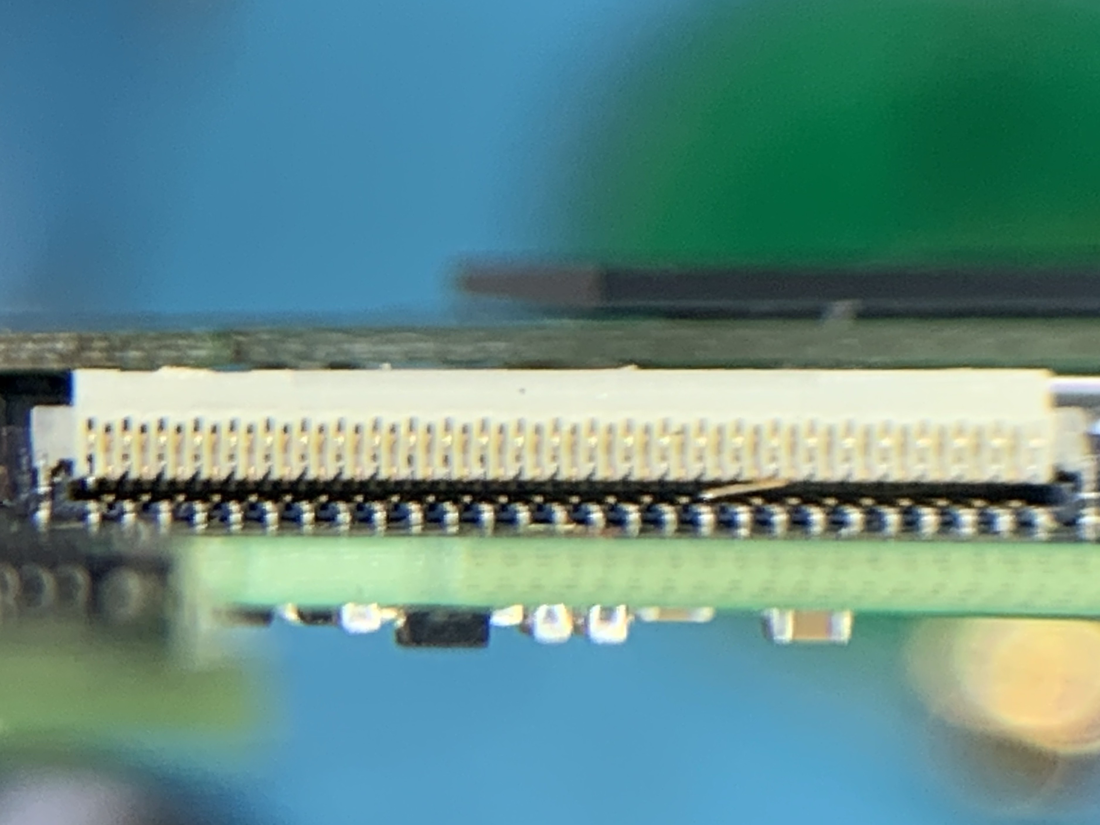
I seem to have the worst day with FPC connectors. I replaced a LCD screen and wondered why there is black screen when booting up. After inspecting the LCD connector I noticed one of the pins is horizontally bent. I am very careful with these ribbons and connectors and still this happens… this is one of those days when I reconsider changing hobby. Knitting sounds good.
The bent pin is from bottom side. I think it does not connect to anything, so I can just pull it out, right?
![]() haha, don’t worry about it man, a lot of people new to repairing switch’s have trouble wth this connector and sometimes it just takes a few tries to get a feel for how to slot it in.
haha, don’t worry about it man, a lot of people new to repairing switch’s have trouble wth this connector and sometimes it just takes a few tries to get a feel for how to slot it in.
tbh it’s not even totally your fault, these Molex connectors are poorly designed… this was part of a “new series” of connectors according to Molex in one of their press releases… translation > “this is a poorly designed connector that has not been properly trialed elsewhere or have a proven track record and is likely to be unreliable”
If you can bend the pin to a point where it is not touching any of the other pins and then test the corresponding pad at the back of the connector in diode/resistance relative to ground and it show OL (in both polarities) then it would suggest the pin is a no connect (NC) and it’s safe to just remove it, I’d wiggle it until it fatigues and breaks off.
On ribbon reinsertion/s, just keep the ribbon as low as possible in the slot trying to keep it as parallel as possible, if you feel any resistance at all just back it all the way out and try again, the pins can only bend if you take them past a certain point of force when pushing the ribbon in, if they never get the force they’ll never bend ![]()
btw did you have any joy replacing the SD pin?