Hi guys,
new Switches, this time with the famous BSOD 
One is a Switch Lite, the owner said that the Switch felt on the ground and was then showing a blue screen. When i press the back cover it starts and boot up normally. Would you give it a chance knowing that i have no experience with SOC soldering and if yes, what would be the best approach to attempt a reball of the APU ?
The second doesn’t seem to do anything even pressing both the APU and the RAM modules, that Switch was kind of abused, the case was bend and not in a pretty good shape.
Thanks for the advice where to start looking at.
1 Like
Hi all,
Found this thread which contains a lot of valuable information. Will keep you posted.
https :// www . tronicsfixforum . com/t/nintendo-switch-blue-screen-of-death-bsod/5311/16
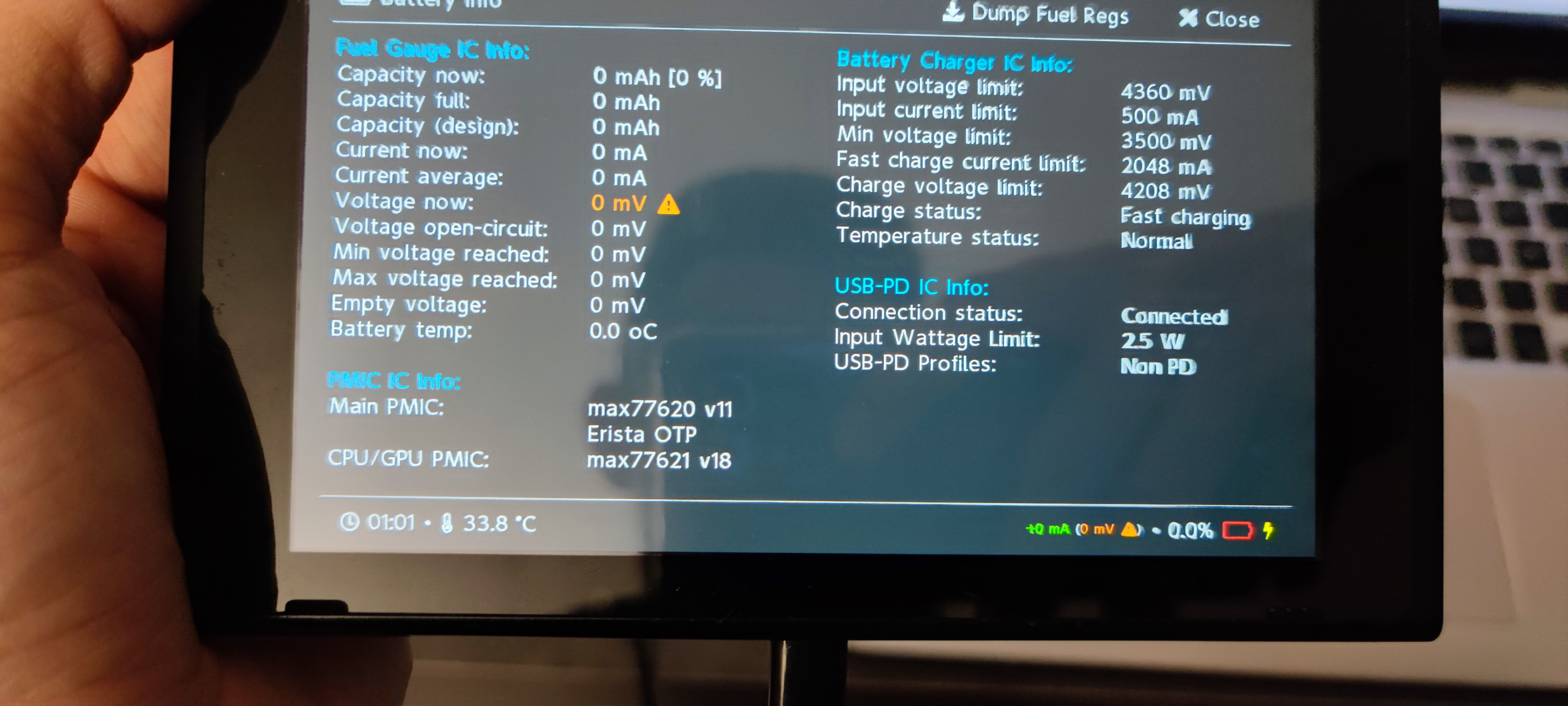
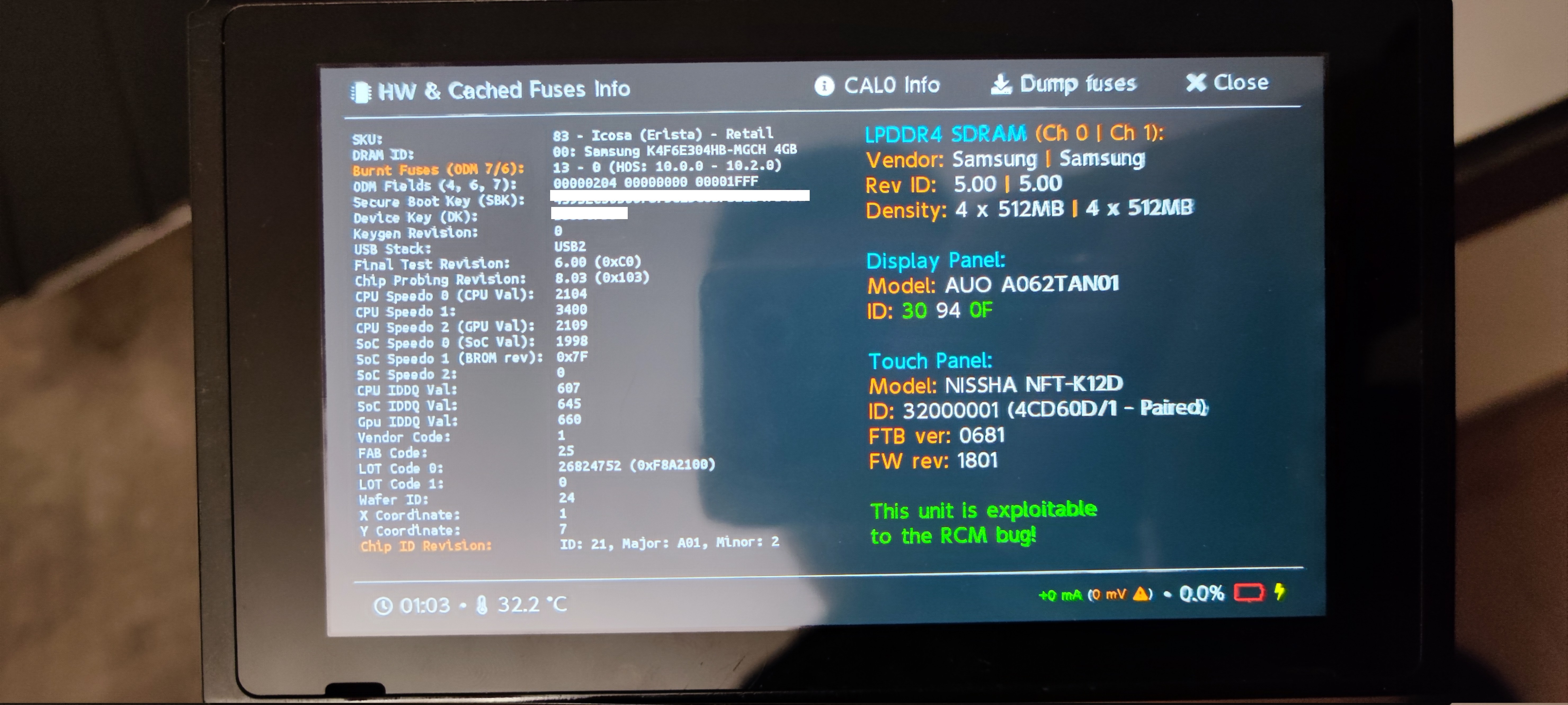
Hi guys, ok started my investigation about the regular Nintendo Switch with BSOD. I removed the EMMC and tried to inject payload which succeeded, and i am able to boot Hekate. Unfortunately, the screen is cracked half left, and therefore i only see the right part of the screen and touch also doesn’t work. So far that’s where i am standing, the most interesting point is that when i am in Hekate, i see no charging current to the battery and no information about it, even if the battery is a bit charged. Could it be that the BSOD on that Switch is due to a bad fuel gauge ? I tried to reflow it, no success, same behavior. Thanks for the advice, and happy new year to everyone, all the best for 2022.
Hi, be very carfull when reflowing the Tegra. Dont use to much heat. Use a big nozzle for your hot air. Heat up the back of the board to 350C for 2min. Then flip around and Heat the tegra for 2-3mins. Put (good) flux around the Chip and Heat up to 400C until the solder at the frame melts. Then very carfully tip the edge of the tegra from the side. It should move to the side by 0,5mm or so.
Of course you have to remove the cap from the tegra at first. Make sure to not crack any components around when doing this.
1 Like
Thanks for the advise, here i was more asking about the Switch that gives a BSOD when trying to boot normally, but looks to work in Hekate normally besides that there is no charging info (0mA) and 0% battery info. Could it be that the fuel gauge is the culprit in this case ? I ordered some anyway, and a new screen and touchscreen, so that i can read the rest of the information.
Did you measure if the Switch is loading? If not it could also the bq or m92. Otherwise i would give the fuel gauge a try.
That’s right I didn’t checked the current, I was focus on the blue screen … I will check that tomorrow, however I checked for shorts and I didn’t find any around m92 and bs for sure…
So the current are in 15V 0.48A both USB-C direction and in 5V pretty much the same, 0.46A both USB-C direction. Does it give a lead ?
By the way, i had a question, can’t we reflow the SOC from beneath the board, by heating from the back ? I was wondering because i apply this technique for all connectors so far with success, so i wanted your opinion on that one. Thanks.
I was told before that the airflow needed causes issues with all the caps on the other side, but I haven’t tried it.
Hm no Quick Charge, but i guess this is normal for a bsod. At least it is doing something. Also as hekate is booting i wouldn’t expect any major problems with the soc itself. A defect m92 wouldn’t cause a BlueScreen. You can Boot a switch without a m92 (so you can remove it for testing) and it should Boot into an error Code. A defective BQ Chip can cause a BlueScreen. At least i’ve read about it. A defective fuel gauge normal cause a blackscreen (but this is also just something i’ve read about anywhere). Can you read the emmc using hekate? I think i would try to desolder the M92, than the BQ (if it then stops working at all i would put it back on, or better replace it) and if this doesn’t help i would reflow the soc. I guess doing it from the back need very much and long heat. From the Front it worked very well for me as long as you are patient, not to hot and Do not burn the Chip in the middle.
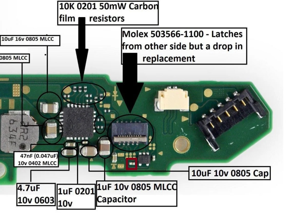
I will diagnose all that, but first, I don’t know if it is related (guess it’s not) but i noticed that i am missing a capacitor under the joycon connector near the BQ IC. Can anyone help me getting the value of it ? I searched the last 2 hours all over internet, i found guys asking the same questions, but no answer 
In the meantime, i anyway tried several things now that i got my functional screen assembly. I am able to boot in Hekate all the time, but it doesn’t seems to be running stable. I always get a frozen screen after a while, and if i try to insert the Emmc, i get immediately a freeze. I will try later the emmc on another working console if they can boot in hekate but this is what i have been able to collect so far. The fuel gauge seems to definitely have an issue, but could it make Hekate so unstable ?
If you are trying to plug the emmc in while it is on, do it before injecting. Note, its not without its risks in general, but I also found it would crash if done while hekate was running.
Definatly replace the fuel gauge.
Thanks for the feedback Insomniac, the fuel gauge are ordered since Monday already, hope it will be fast to get them. Regarding the emmc before injection, I will give it a try, I saw TheCod3r doing it, so I tried myself too
By the way, no-one for the capacitor can help ?
I make it 100uf. Thats in circuit on a board with most chips removed, including the soc.
awesome, thanks. as soon as i receive my Max17050 i will put everything in and see what happens.
Hi, today i checked in my 0201 capacitor book, maximum was 100nF, isn’t it wrong 100uF ?
Hmm, well measures one way it 65 uf, and the other 100 uf… I probably need to measure it fully out of circuit.