Hi everyone, I bought this board to practice on, the owner claimed that it worked before but while trying to dump the bios he knocked some components with the soldering iron.
There were 3 missing resistors and one was missing a pad.
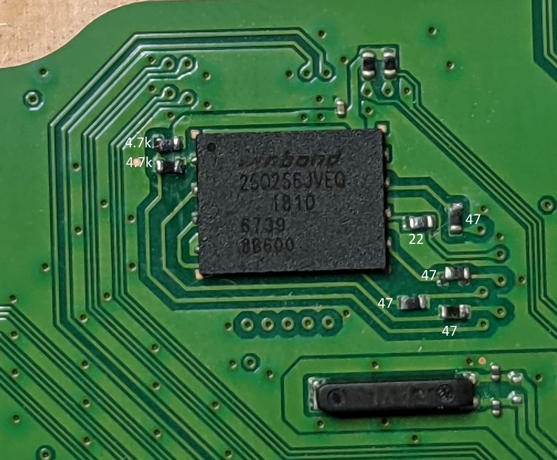
Unfortunately the boards that I have have only one 4.7k resistor on pin one, so I don’t know if there are supposed to be two resistors or a resistor and a cap.
Right now the board does not power on at all, it has 3.3v on the power button but when I press it the 12v does not enable. Which, as far as I know it is a southbridge issue.
Thanks.
Thanks for the help.
Unfortunately, I already did that, I get 3.3v on some and slightly less 3.298v on others.
As for the break in the lines, did that too, that’s how I found the resistor with the missing pad and how I found myself with two 4.7k resistors on pin one.
One was missing, the other read around 50k, looked on the boards I had and there was only one 4.7k resistor there. Didn’t turn on, checked for continuity on traces and that 50k resistor gave problems.
Removed it and noticed the missing pad, but after trying for a while it gave a 4.7k reading.
I don’t think that’s the problem, the voltages were read directly on the pads on the sides of the NOR.
Plus, I soldered the resistors without the air station on purpose to not stress it, and I don’t think the seller used an air station either, he soldered the wires directly on the resistors.
To be honest, I think that he lied about it working before the NOR dump, the only reason to do this is to enable UART. But since I don’t know what components are near pin 1 I can’t be sure.
The variance in resistance is probably because of different revisions, the ps4 fat SAC-001 board (also one 4.7k resistor on pin 1 ) that I have has roughly the same 20k resistance, the only difference was in diode mode, 0.528v vs 0.582v
Yep, I had to put a jumper wire, otherwise it would not complete the circuit.