Thank you so much!
I am grateful, you just saved me!
I think the size is 0402 I will take a resistor as a sample and double check it.
One last thing I would like to verify has to do with 2 tiny caps (the one which is underneath the 180k resistor and the one which is placed right next to 200k resistor) are 1pf each correct?
120pF from datasheet, I didn’t check. Very likely in pF range(under 1nF)
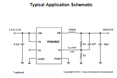
From the datahseet Cff equation R2 is 59k instead of recommended 100k value, I guess Cff will become 200pF IMO
1 Like
You are awesome!thank you very much!
Thanks a lot for all this informations @jkyoho and @nikoska
I have a problem in this area too, maybe it can help others if we found the answer, so i post it here not to duplicate posts.
If i understand right how TPS62822 (A2 chip) works, they needs an Enable voltage (Pin 1) to use the 5 volts Vin (pin 7) as an input and generate 3.3 volts output for one, 1.8 volts for the other)
Found that Pin 8 of A2 chip cpu Side is connected to the pin 1 of A2 chip Vram side. So 3.3 Volts generate by the A2 chip on it’s last pin (cpu side) is the enabler for the A2 chip on Vram side (1.8 volts)
In my case, i need to find where the A2 chip cpu side pin 1 goes. In others words, what is enabling this chip on it’s first pin ? Making many mesurements, unable to find where this trace go.
Need to know it because my A2c chip (cpu side) got 5v input, but nothing output, and nothing on the enable pin. Without this, the chip can’t be enabled, and not making 3.3 volts for the other A2c chip, and generating 1.8 volts at the end.
Thanks a lot !
Dont have a edm-020 board by hand, but from TPS62822
datasheet Page1, Enable pin/pin1 is directly coming from Vin which gonna be 5v_standby.
Thanks bro I have that chip when I install it, it was drawing 550+ma however that area shows short but when I inject voltage into it I don’t see anything getting hot it draws over 2 amps either side of the capacitor. Any idea what could cause it?
I just found this on AliExpress:
1PCS TPS62821DLCR TPS62821DLCT TPS62822DLCR TPS62822DLCT TPS62823DLCR TPS62823DLCT TPS62840DLCR VDFN-8 PMIC
ttps://a.aliexpress.com/_m0MojsF
Put in the h