Hello,
i hope there is someone out there who can help me fixing my problem:
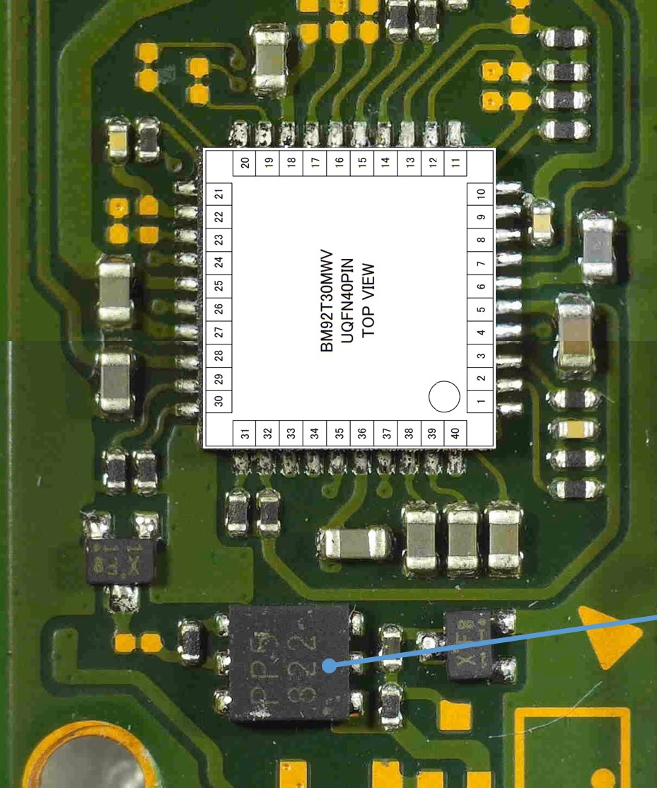
History of my switch: It is unmodified. It worked proper until the day the switch was not charging any more. I tested the normal Switch charger with an 5V and 15V output. Nothing happend. I plugged it and nothing happend. So i tested a mobile phone charger with an 5V output only and that worked. With the 5V charger it charged to 100%. Great. I did that two or three times and someday i saw the switch battery is low so i plugged it in and after 10 minutes i touched the charger and it was hot. The USB port at the console was hot, too. I plugged it off immediately but the usb plug was melted with the usb c socket at the console. So, the first thing is to change the usb c port, which is already done. I found a picture in the internet where the values, measured at the usb c port, if soldered are written. I have other values. So i moved forward to the typical “searching for shorts” method, and i found nothing shorted, but there is one capacitor in the area of the M92T36 that is not connected to GND. I measure on one side of the capacitor a value (in diode mode) of 0,684 and on the other side a value of 0,615. I attached the picture, showing the position of the capacitor (the measuring tip is marking it). Now the question is: are these values normal? Shouldn´t be this capacitor connected to GND?
I hope someone can help me fixing this.
Thanks in advance. Best regards.
Unfortunately I can’t attach files, I try to find another way to make the pictures accessible.
Debugging failing ICs by checking for capacitor shorts is pretty unreliable in my experience. Sure, if you find shorts, it’s a dead cert, however there are plenty of failure modes that don’t result in a short. Particularly with the M92. What voltage are you getting on M92 on 5 and 6 with USB power connected? Have you checked the fuse for continuity?
Hello,
yes, I checked the fuse. It has 0 ohms (or nearly).
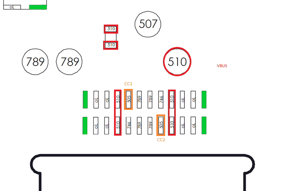
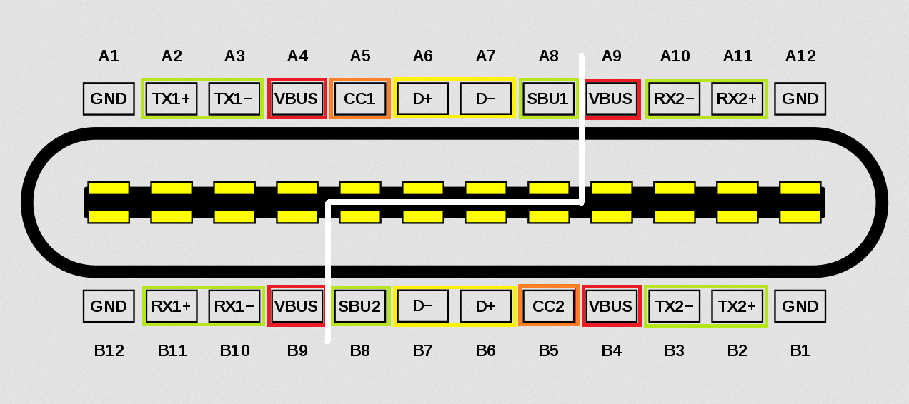
Sorry for asking a stupid question like this, but I want to make sure that I measure at the correct pins. How do I count the pins of the m92?
htt*s://www1.xup.in/exec/ximg.php?fid=48736814 is this correct?
Best regards
Hello,
I measured at at pin5 (+) and pin 6(-) in DC mode: 0,15 v at the first try and 0,07 v at the second measurement. My set up was: switch power supply (5+15v) and a connected battery.
Best regards
This is typically as a result of bad M9 IC or soldering/bridges on the M9 IC, remove the M9 IC and you should get your 3V3PDR back on pin 6 of M9 indicating one of the two above.
Just to make sure. You did put one probe on pin 5 or 6 and one on ground, right? I would guess that if you measure the voltage across pin 5 and 6 you the result is close to 0.1V
Yeah, Likely your M92 replacement or soldering at fault. Remove the M9 IC and ensure no bridges across any of the pads on the board or elsewhere and measure the voltage again, i imagine it will read 3.3V as it should
Also, check the voltage on either side of the fuse (relative to ground) above USB port if you haven’t done so already before and after.
Hello,
What I understood is: I have to measure from housing of the usb c port (GND) to the both sides of the fuse. I did, and there was nothing, 0,1v. So I put the + into the red wire of the connected battery and measured to GND, 4,15v.
To fuse bottom side : 4,1v
To fuse top side : 4,1v
To pin5 and pin 6: 4,1v.
I also tested again the usb c multimeter but it shows nothing. If I connect the power supply, including the USB multimeter to my phone it shows 4,95 v. That means Multimeter and power supply are working. My resoldered usb c at the switch Mainboard looks good to. The multimeter doesn’t show anything so that means the soldering is bad or there is something shorted on the MainBoard.
I am confused.
Best regards
I would unplug the battery and powersupply and test in diode mode at the usb c port for plausible values.
(Red probe on ground and with the black probe at the pins. It is importend which way around the probe are!)
Without a breakout board you might only be able to measure the first row directly.
That’s correct, Instead of using the USB as your ground, instead use one of the boards screw hold pads, as they’re “gold” plated they’ll provide a better reference and rule out probe issues elsewhere.
Sorry i don’t understand what your doing here, afaiu your not using a ground as your reference so the results would be invalid here.
Just stick your black probe on ground (screwhole pad) and use your red probe to measure the voltage at various points (Either side of the fuse for example) if you still have approx 0V present here, then disconnect your battery and USB and measure continuity across it.
After follow Calvins instructions after and test your USBC, preferably with a breakout board