Newbie Question - LCD Not Longer Working After USB-C Replacement - Sounds, No Display

Hi,

First I’m going to say I’m quite the newbie to this. I’m going to start from the start here.

I bought a faulty Switch Lite from eBay. Reportedly needing charging port replaced. I replaced a fault USB-C port on the Switch Lite. It worked but would only charge on one side. I took this to mean the hidden pins maybe didn’t make a good connection. But also I found out once it booted up that the right stick was needing replaced also. Took this as a good excuse to try and fix my the USB-C issue.

Re-placed the port to see if that would help. Installed the new stick. Put it back together. However I get no screen, only sound. And I don’t think the Switch Lite boots up unless it’s plugged into power. My Amp Meter is showing around 0.6-0.7 amps when it’s on.

Does anyone know what I can do to check this out? I’ve tried reseating all the cables and cleaning them incase I maybe got them dirty. But nothing seems to help. I’ve got a multimeter. Is there any readings of components I should check at all?

As I said, I’m quite the newb to such repairs, so I kind of need it explained in layman’s terms also haha.

Thanks for any and all help. It’s greatly appreciated.

image

Turn the switch on, place a bright flashlight near the edge / corner of the LCD and see if you can see the home screen. If you can then your backlight isnt turning on, and that is most likely due to a bad connection at the fpc connector that goes to the daughter board. To test for continuity between the boards take a look at the above image (thanks @jkyoho) test the pins on the daughter board to the pins on the mother board (both on the connector and to the passives north of it leading to the backlight circuit). If i were to hazard a guess, knowing nothing else, id say you dont have a good connection on the orange points.

These fpc connectors are stupid fragile and it doesnt take much to warp the white clamp that holds things in place. You can also do a quick visual inspection of both the backlight flex cable and the cable which connects the two boards. Look for any breaks or corroded pads that may have been eaten away. Usually only an issue with liquid damage units, but never hurts to cross something off your list.

I don’t see anything with a torch unfortunately.Should I try checking those connections anyway?

yes, it never hurts to rule them out. Ive had a few ive repaired where it seemed like the screen / backlight was dead but it was all related to one of those two connectors / cables needing a little love.

Sounds like the LCD Connector went Bad.
They are very fragile and the pins are easly bent or breakable.
Check this connector.

if you can get some images of the connector and the pins etc sometimes a third eye can spot an issue you may be missing :slight_smile:

Thanks guys. I’m using a third hand with magnifying glass at the moment. Got a microscope on the way and hopefully that will help. Here’s some photos I was asked to get of the port. Apparently the fuel gauge has an issue and can cause issue with charging AND the display? Here’s a probably not so helpful one of the connector.

https:// imgur .com /ywDpwm6

https:// imgur .com /QOCzWIq

https:// imgur .com /S9Eyz9N

Oh and a video of the ampmeter when I plug it into the wall.

https:// imgur .com /a/RFnoq2Z

To Check the LCD Connector, please make a photo from the side, showing the inner pins.

If the fuel gauge is Bad, the switch will not Boot at all. But it will normally only draw 0,4 amps then.

Hard to Tell what’s going on with the amp Meter, Never had this. Looks like it’s slow charging First, then fast charging but both values are much lower than they should be Maybe not All pins from the usb Port are soldered on correctly

MAX17050/FUEL GAUGE IC doesn’t look good to me :joy:

Ahh ok. Yeah it definitely boots as I can hear the noises of the switch through the speakers.

I’ll need to wait until I get the microscope. My phone can my focus on the connector to get a good photo. I’ll take a screenshot with my new microscope on Saturday.

As a complete noob. Can you explain to me what looks so off about it? Apologies for the silly questions. :joy:

From the pic the fuel gauge ic seems to have a blob of solder been squeezed out. Need a better picture

Hello everyone, I had an identical problem that took me 6 months to understand the cause.

As far as I am concerned, I had disassembled the motherboard to replace the USB-C connector.

So, I have necessarily disconnected all the tablecloths.

After reassembly, no more image!

However, I had a correct load.

Finally, I gave up.

But the same problem has happened to me 3 times lately (with different serial numbers and different colors of Switch!).

When I reassembled these consoles, I had to reconnect everything. Even the speakers!

And it was thanks to them that I was able to understand part of the problem, yes…

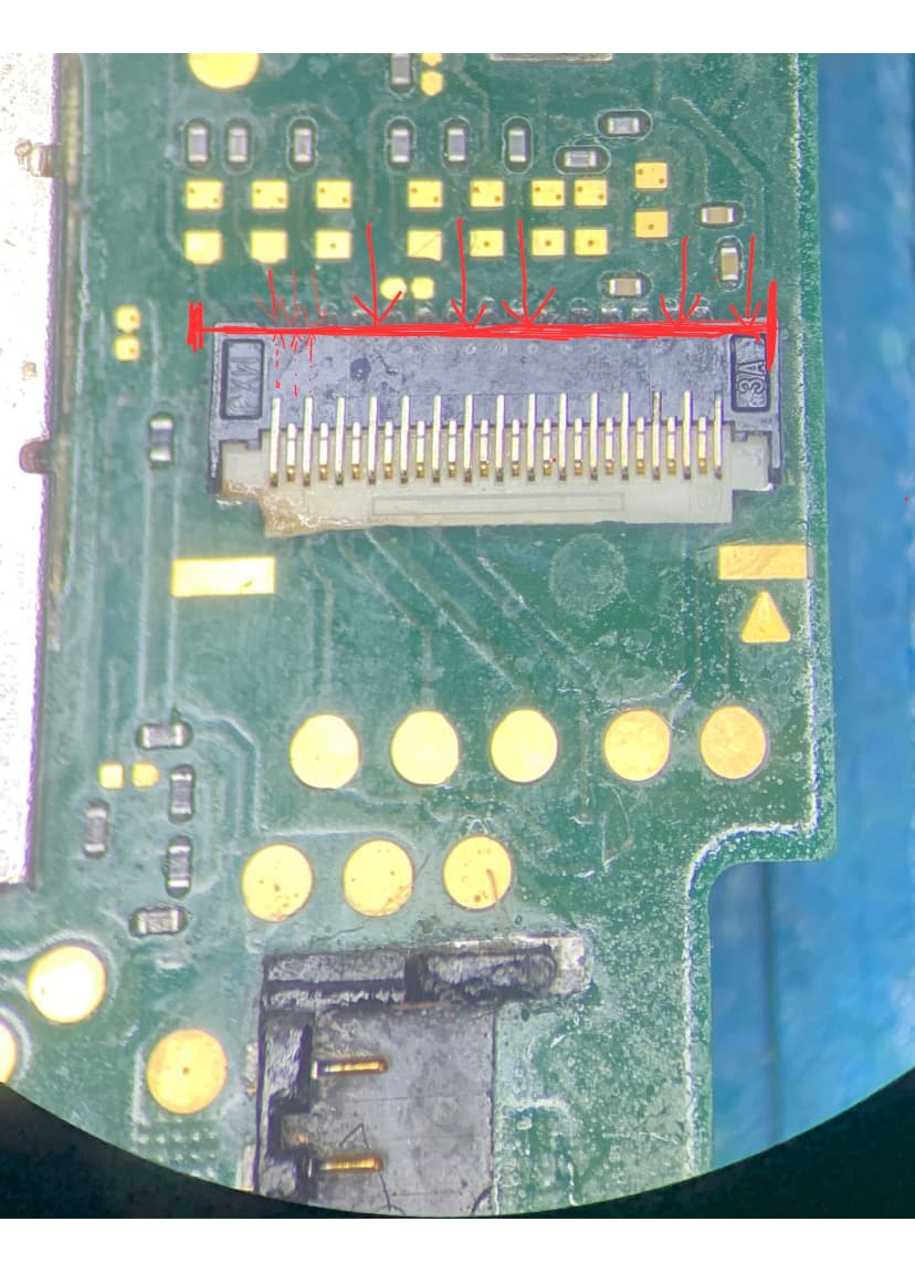
The reason: the resulting flex cable that brings the backlight from the daughter card to the motherboard (passing under the battery) arrives in the FPC connector which is just above the battery FPC connector.

When you insert the tablecloth, it often happens that you push harder than you should! This has the effect of pushing back the golden pins inside this connector!

It will only take 0.5 mm to make a mess (believe me, it took me 6 months to realize it and 3 Switches to check my theory!!!)

My advice:

  1. Carefully handle the locked locquet of all these flat connectors!

  2. Gently insert the cable into the connector without forcing too much.

  3. Check (under a microscope, if possible) that no golden pins stand out on the other side of the connector.

  4. If they stand out, gently push them back into the connector with a clamp or flat screwdriver.

  5. Then, lock the connector using a spatula so as to cause homogeneous support along the entire length of the latch.

NB: Don’t forget to reconnect the speakers because they will allow you to hear the sounds of the touch in the event of a black screen.

What I hadn’t done when the initial problem occurred!

This method allowed me to recover the backlight, and therefore the display of the images on the screen on 3 other SWITCH LITE ONLY!

WARNING: This method only works if the cable has been manipulated.

There may be other reason for your problem that this method cannot solve, but it’s worth trying!

I put an image of the connector in question and the red line indicates that no pins must come out beyond this limit.

The pins must be INVISIBLE when you look at the connector from above (under the microscope, of course!).

I hope my experience will help you get out of this situation.