Pin 6 and 7 are the ends of the usb 2 datalines. Maybe I m wrong, but If You measure OL above the filter, then there is no connection to the soc and it doesn t matter if the usb c is soldered or not.
I think there is a misunderstanding, I expressed wrong… Sorry
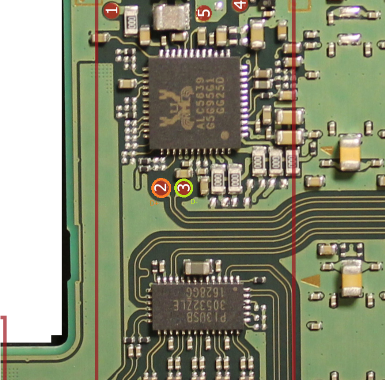
pin 6 and 7 of the usb c connector does have continuity in the filter(and so the d+ and d-) . From the photo you sent me: orange is continuos only on the left of the filter and green only on right.
@jkyoho sent a photo of the diode values to ground and in pin n. 7 i should get .755 but i get 0L even if the any of the pins aren’t loose
Hope it’s a little more clear now
Ok. If You turn the board on side A, You see the same test points. I would measure in diode mode the both points. If You get OL at one of this two points, the problem is at the soc.
…or on the path to the soc. Maybe a scratch.
I get 0L from the d+(2) and ground, on the d+ of side A is the same . So you think I should change the socket?
In my eyes the cause of the open line for d+ is under the soc.
Maybe You should ask FXDX for advise, if You want to reball the soc.