I recently got a switch which did not turn on (black screen and could not enter hekate). Then I check and compared to the switch diodes of the board and found the audio IC has an issue, after replacing the audio IC, the switch booted but in blue screen of death. I measured the resistance of the various power rail with a fluke meter (black on ground and red on the inductors). Please let me know if the audio IC caused the blue screen? or should I look else where. Thanks
Audio IC never went wrong. Likely there was a short causing it not the power but the audio ic does not cause blue screen of death this is caused by the cpu if you put pressure on the cpu and the consoles boots like normal then a reflow will more than likely solve this issue. If it continues with a blue screen a reball is usually what is required but not always a 100% fix
1V8PDR is too low, so you have an issue on that rail…
The Realtek IC is not on this rail afaik (but I’d double check that)
Check your 3V3PDR resistance to ground also. If it’s fine then start by removing the EMMC module and see if that resolved the low reading if not then remove the M92 IC and see if it that resolves the low reading, if not then try removing ram if not that then there are a few other ICs on the board on 1V8PDR but typically it’s SoC at this point.
What lines on the original audio IC gave bad readings in diode mode? as it may give clues
I am not 100% sure, since I had a blackscreen before replacing the Audio IC, after replacing it, then it booted up into a blue screen now. I have reflow it once and it’s still the same. Thinking about reball but I do not have a bottom pre heater or a bga reflow system.
I was getting around 750 in diode mode before. After replacing the chip, I am getting around 1500~1600 in diode mode.
For the 3v3PDR, I am getting 190 kOhm on m92 pin 6. but on the flip side above audio IC in red dot, I am getting 159 kOhm
What should my typical readings be on the 1v8 and 3v3? Could the Max chip south of the APU be causing an issue?
This line is related to headphone and is likely not the real cause of the primary fault, I would guess your heating of the board changed the symptom status, While the Realtek IC may have been bad it’s unlikely, it’s far more likely somebody before you reworked it improperly.
That’s fine.
on 3V3PDR it would normally be anywhere from 13K to 20K to ground and if the junction is triggered then the same as your readings or fluctuating high megs (normal) this is not your issue.
on 1V8PDR, on a meter which is giving the correct results you should be measuring anywhere from 9K to 13K depending on probe polarity to ground. But as I’ve mentioned before, you first have to verify you get this result on your particular meter on this rail on a known good board.
Cheap manual ranging meters and even autoranging Flukes have an odd measuring frequency and forward voltages which changes drastically between models and in some cases can seriously skew readings, so it’s best to verify you meter is taking these readings properly before taking any drastic action.
you mean the SoC? it’s possible, I believe it has a connection to 1V8PDR, though in my experience these Max ICs don’t fail often and if they do it’s normally as a result of physical damage (cracks/chips) or because of liquid/corrosion under it
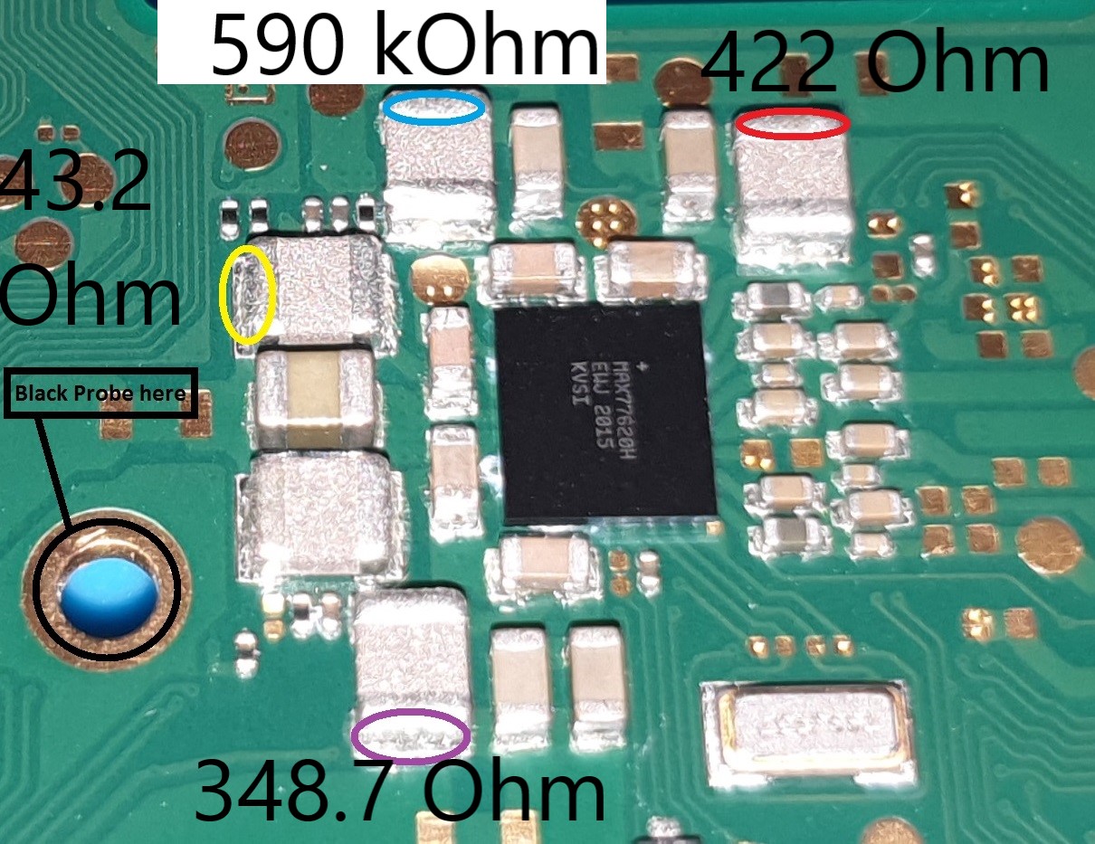
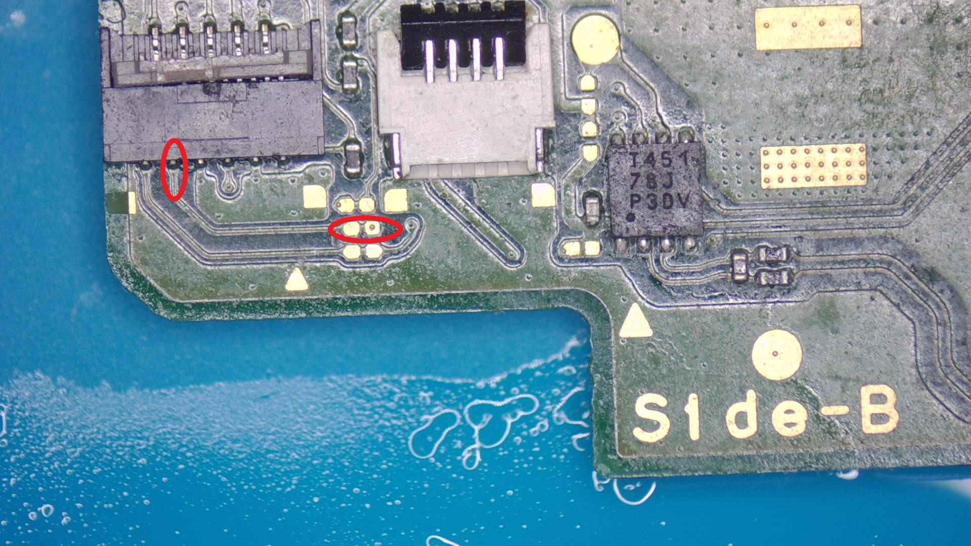
On the 1v8 (red circle)
Good Switch: 21.61 K Ohm
Bad Switch: 21.91 K Ohm
On the 1v35 (blue)
Good Switch: 0.695 M Ohm
Bad Switch: 0.663 M Ohm
On the 1V (yellow)
Good Switch: 47.3 Ohm
Bad Switch: 43.9 Ohm
On the 1V15 (purple)
Good Switch: 350.7 Ohm
Bad Switch: 350.0 Ohm
Oh, I see, what should be my course of action? does EMMC cause blue screen as well? or should I take out m92 + p13 > then reball ram > then reball emmc > then reball SOC ? or is there other faults that could caused blue screen ?
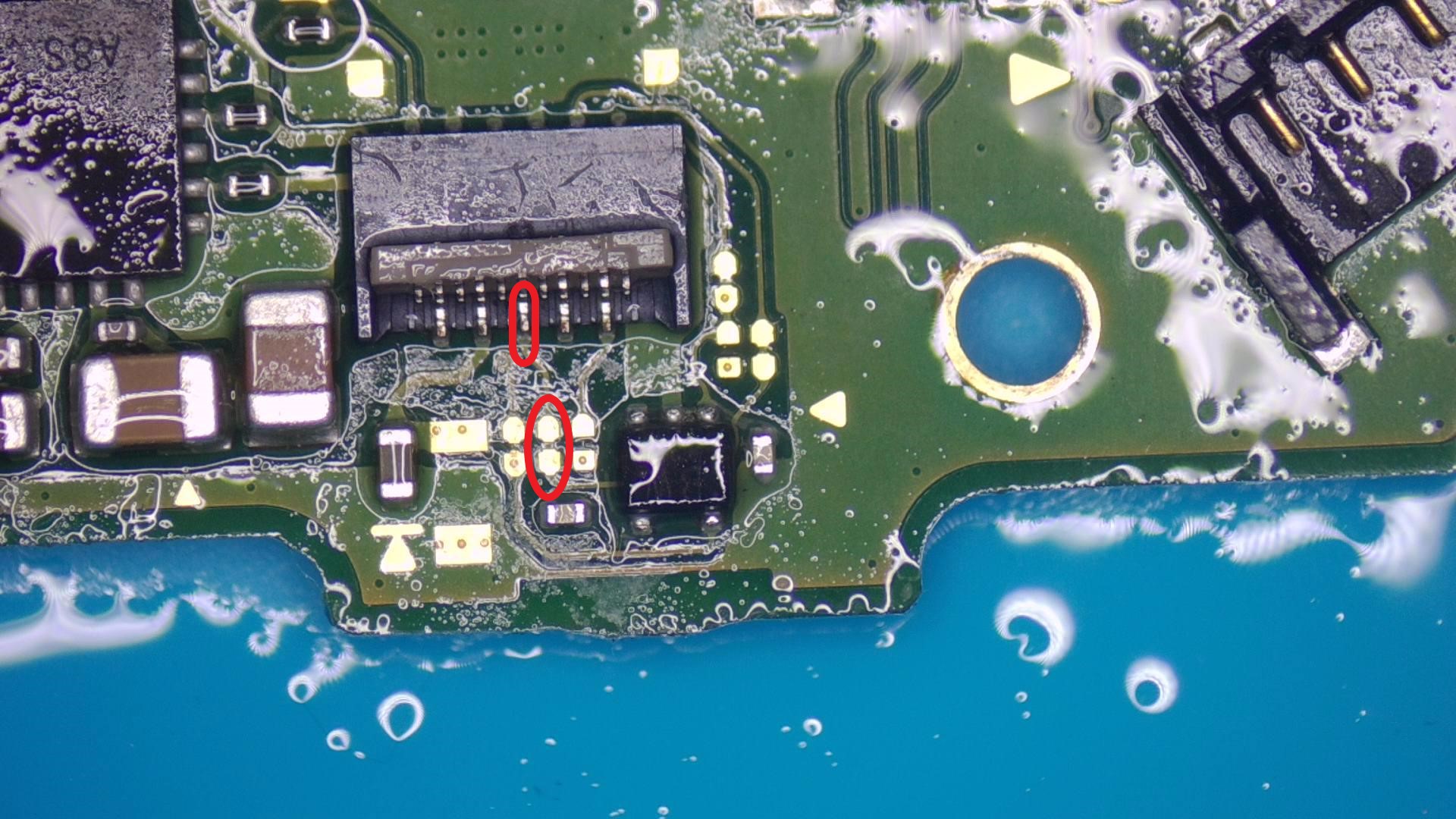
On a side note, my joycon fpc connector (circled in red) shows a slightly lower value
Good Board: 700 to 740
Bad Board: 555 to 558
Would this give hint as to what is failing
Ok, your meter isn’t giving an accurate in circuit reading but the rail is measuring fine (representing more of an open than a close) compared to your known good, as such it’s now no longer a concern.
What is concerning is your reading changed from about 422 ohm to about 21K… why? was this after reorking the audio IC again or have you done something else between these measurments.
The other rails are measuring fine and are not of concern.
It can do, but it’s rarer than others would have you believe and can be due to corruption of certain partitions, I’ve seen it less than a handful of times.
I don’t take diode mode measurments (which I presume these are) unless I’m expecting a gross failure, pass/fail situation…more often than not it’s a pointless check as in situations such as yours above any value in between a “good” and “bad” reading is too vaugue, in circuit resistance [to ground] measurments are effectively a high resolution version of a diode measurment putting it loosly and if your meter is fast it seems to me a bit pointless why anybody would be using diode mode readings, unless as I said as a quick pass or fail…
Well first port of call for me in BSOD cases is Fuel Gauge, then Ram then main PMIC, after that it’s typically the SoC.
Ram failures typically occur due to joint issues after poor prior rework of the USB port and/or the M92 IC and the ram ICs themselves rarely ever fail and can be reflowed in some cases but I typically reball as a matter of course. you can reinforce ram failures such as this by measuring the resistance to ground in both probe polarities on the two rails which the ram sources it voltage, which is 1V15PDR and 1V8PDR and comparing to a known good, a bad joint issue will typically show a marginally higher “open” reading compared to the known good
For the fuel guage you can check resistance to ground on the surrounding components and compare to a known good, but more often than not they will test fine (even if bad) and fuel guage failure is typically physical damage and any chip or crack around the edge etc (however small) can cause such symptoms.
PMIC is harder to narrow down as the cause, I have simply to little info on it and while I have a few spots and ideas as to what to test I ultimately haven’t documented it in detail to give a concrete conslusion on this, more often than not it’s simpler to pull it, reball one from a donor and plonk it on but practice is needed, most beginners will crack or chip it on first attempts.
1 Like
Sorry, I think I got the 422 Ohm by mistake. I have another issue, when i put the black probe on ground and measure 1v8 rail, the first reading is 5 K ohm and if I take another measurement again I get 22 K ohm. I am not sure why the intiail one is so low and if I confirm on the same point again it jumps to 22 K ohm.
So black to ground and red on the capacitor/resistor in question to measured in resistance mode?
So even if measured resistance show no abnormality, the fuel gauge IC can still be bad?
how would one avoid cracking it or shipping?
Thanks for your help.
Just to confirm, this isn’t a Mariko board is it?
I wouldn’t worry too much about the inconsistent readings, as from what I’ve been told by others this seems to be pretty inline with what I’d expect from a Fluke. Also, if you’ve been powering the board up (which you should refrain from doing until your satisfied the fault has been resolved) then temperature will have a significant impact on in circuit readings, even if the board is only mildly warm.
Yeah, though you’d be comparing it to a known good as I have not propely documented this area and don’t know off the top of my head what rails/lines this is ultimately connected to.
Right, and that’s because an internal failure of an IC can affect the internal functionality of the IC (communication for example) without affecting outward accesible lines, but as I say, you’d typically verify this in the form of chips or cracks or liquid/corrosion below.
Mind you in cases of BSOD switches, I’ll replace the fuel gauge regardless of whether I can see physical damage etc as it’s easy enough to rework and they ICs are cheap. Chances are very slim though if it’s physically fine and measures fine on the surrounding components but, cheap and simple, so I like to rule it out.
practice on donor boards, do it 100 times if you have to, doesn’t have to be a switch, you could select an old phone or macbook board with a similar packaged IC, and just remove, reball, wick the board then reattach the IC and just keep doing it until your perfect at it.
Decent tweezers, seems most tweezers coming out of China are made of cheese grade steel and are not hardened, as a result most have tips which don’t close together at the very tips which is an issue on these thin profile bare die ICs as they can’t get a good grip and chips and cracks occur. I harden the tips on my tweezers myself with a blowtorch and quench in cooking oil, then I lap/grind them with sandpaper and reprofile the tips to a finer point.
Too much or too little heat/air, this will be adapted for yourself and station during the practice mentioned above.
Another commmon mistake I’ve seen is people trying to remove the IC before the IC is up to reflow temperature, chip still holds on in a certain spot and beginner then desperately try’s to grab it and cause damage to both the IC and sometimes the board pads and/or surrounding components.
Reason I emphasize practice is these ICs wer’e talking about all pretty much reside on primary/critical rails or in the case of the PMIC it produces most of them, a cock up on that IC can kill pretty much everything else on the board if not reworked correctly.
1 Like
It is not a mariko, it is a v1 unpatch ( cannot access hekate due to bluescreen)
How many ohms off is acceptable?
I am ordering a few extra now.
Thanks for the info and the tips. Will update this thread when I get any progress.
I see, try loading the Biskeydump payload and let me know if it boots, and if it boots with graphical glitches
Failing that, try loading the memloader payload and let me know your findings and the error displayed.
different in each case, what’s the difference between your known good board and your currently bad one?
I have loaded biskeydump and it boots with graphical glitches.
I see, try putting downward pressure on the Ram modules and see if that resolves (or changes) the glitches while booted into biskeydump while the power is still on.
Chances are 95% now it’s ram or SoC
If your get an MTC error in memloader payload it’s now 99% ram or SoC at fault.
I tried putting downward pressure on the ram and apu, it still show graphical glitches. What is an MTC error ?
I would replace the ram from a donor and reball (just make sure it’s from the same vendor IE: Samsung or whatever) and then you can inspect joints below, sometimes the pads can be damaged due to board warp or the improper prior repairs mentioned earlier, and the reason for using ram from a donor is simply just to rule that out too
failing that then it’s likely SoC internal damage or even slimmer bad joints/pads below the SoC
Memory training
The other donor boards I have might have the same issue sadly, I am thinking it might be also APU or RAM, what kind of temperature can the APU or RAM take? I’m guessing it’s 450 C to melt the unleaded? Would 450C damage the APU or RAM ? I dont have a preheater… If i had a preheater, is it 200C at the bottom and around 250~300 C at the top (is that correct?)
Thanks
Well the Ram ICs fail very very rarely, in all the boards I’ve repaired I’ve encountered only one bad Ram IC and that was only due to extreme liquid damage and on top of that an extremely bad prior repair attempt, most of the time they’re fine.(after reflow/reball)
In the case of the SoC, you can swap them from one board to the next but they’re tied to the EMMC module so you have to ensure you swap both together else you’ll just burn fuses which creates it’s own set of issues during diagnosis.
This all comes down to practice again, and familiarity with your hot air station as it would be pointless me giving you my precise temps and air speeds but I can’t stress the practice part enough. ![]()
The SoC will not tolerate direct forced air for an extended perior of time, doing so will cause the resin around the die to turn from greyish/blueish colour to a nasty looking brown which causes internal stress and kills the corresponding low voltage rails on the SoC If you see this it’s game over. I typically preheat the rear of the board in stages just using my hot air, 100C for a min or two, then 150C for a min, then 200C for another min, then flip over and direct heat the SoC for 30 seconds, while still applying heat, add flux around the perimeter of the SoC, then I crank my station up to 420C medium air, ensuring the whole SoC nudges I lift with a suction pen.
This entire process is kind of a cheat to remove components outside of the normal capabilities of our equipment and to best emulate a factory reflow process as best we can.
As I say though, temps and air speed will be all very different on your station, chances are extremely high you’ll kill the SoC on at least the first try, practice makes perfect so repeat the process while monitoring the resin/epoxy around the center die before and after a lift.
1 Like
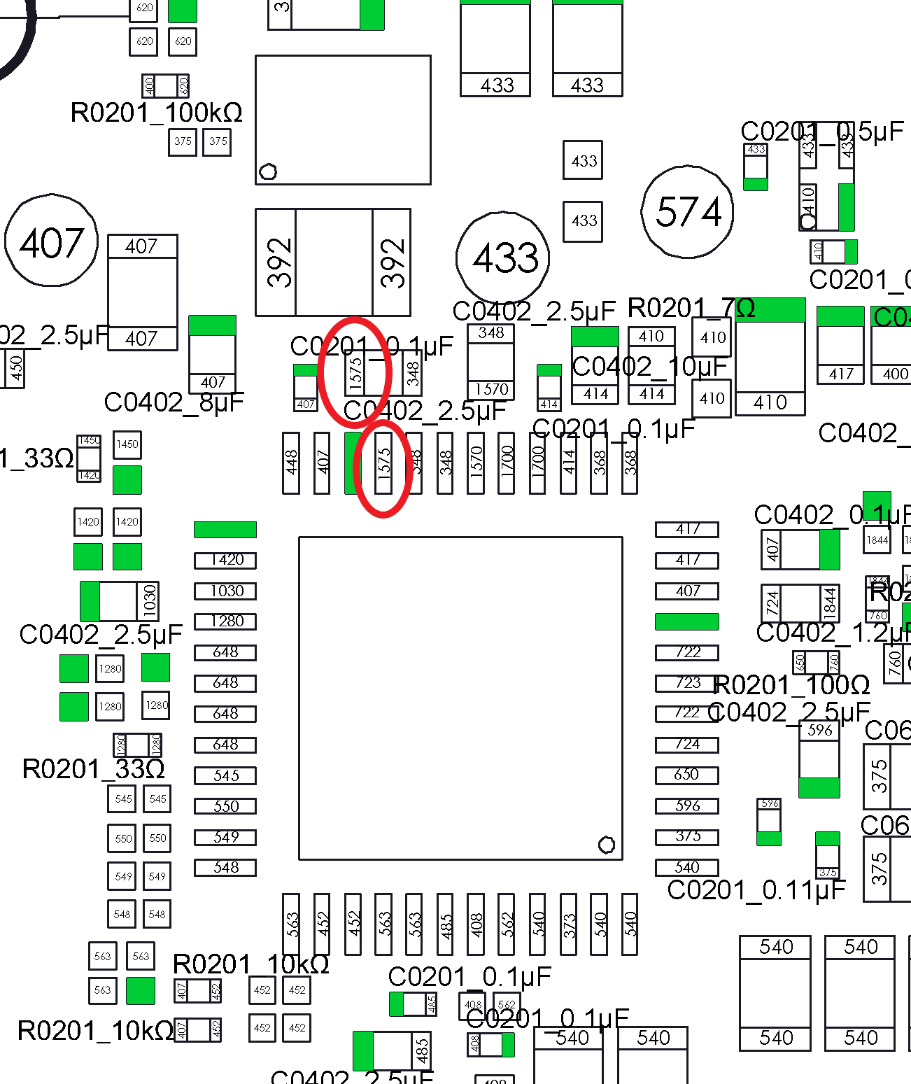
Where did you get that boardview?
Hello Severence. I’ve got BSOD too. Biskeydump payload launch without glitch, memloader payload also but it stucks in “attemping to comunicate with usb host…” Hekate does not boot at all
memloader payload also but it stucks in:
error is MTC_LOAD Error during Lzma decompression, got 0 instead of 429…ecc