So what is the difference in using the stencil vs just using the hot iron? Thanks for the info
There’s too many reasons to list and i think your questions would have better and more detailed answers served by searching for dedicated articles and videos on the subject.
But short answer and most important reason is ball size consistency, if one (or more) of the balls was marginally smaller and the opposing pad/plane is high thermal mass the IC will be sucked down to the lowest common denominator causing bridges/shorts… Or the ball will simply float above the pad and not make proper contact.
The reason for using solder paste and stencils is because as the IC’s are small it’s easier but more importantly it puts the IC under far less stress as the pads on the IC don’t need to be wicked (just lightly tinned with an iron prior) which reduces the risk of damaging the coating arouns pads… which could again cause bridging/shorts if damaged / stripped back.
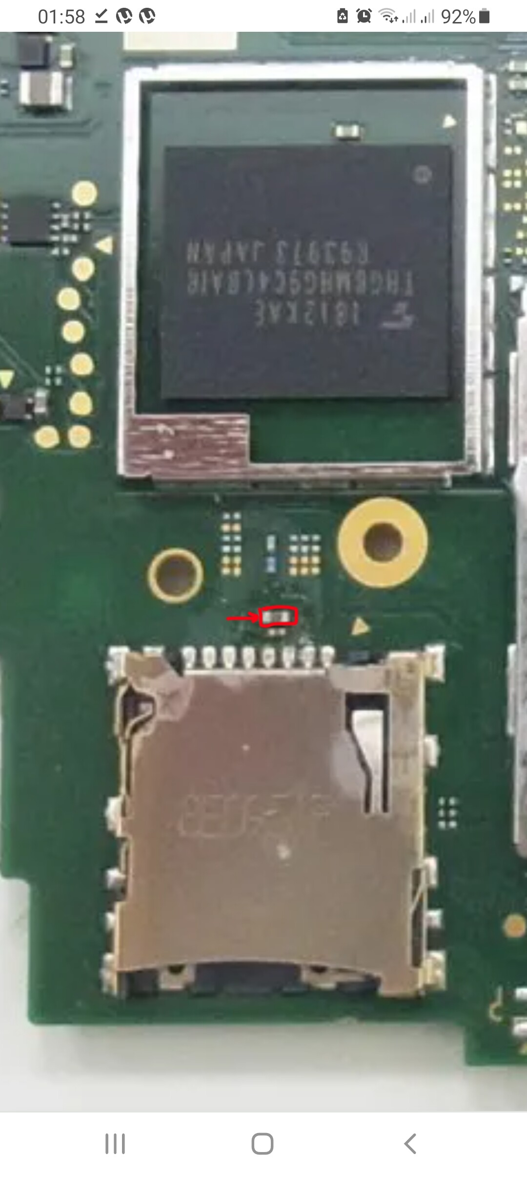
Greetings Calvin, thank you very much for all your contributions, I would need to know if you could send me the section of the lcd connector where all the pins go, I have an OL that indicated in the image that the pad was gone and I could not make the video, I already replaced the connector and the solder are fine, but this OL pad seems to be giving me the problem thanks
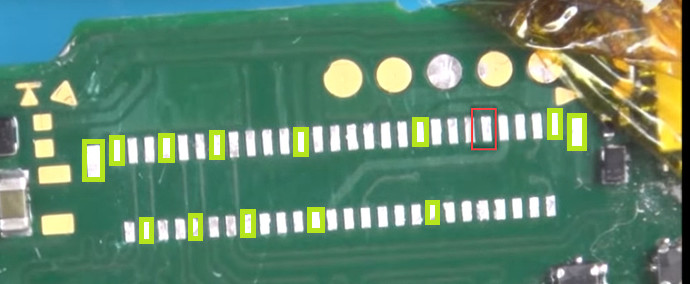
I took this image from another post but there they do not give any result, at least if I know where that pad goes, I can make a bridge and try to revise it, thank you.
The marked pad is nc. I lifted the pad and there is no connection under it to any line.
Greetings Calvin thank you very much, it really has me puzzled because I checked the rest of the pads and they all look good welded, I am also waiting for a new microscope to arrive to verify 100% that this is so, a hug greetings.
Hello, sorry to jump in on this thread. Do you have any pictures on where those primary rails are to check if SoC is bad? Thank you
1 Like
I think they are the caps next to the M9 chip. Though I can’t find anyone to show measurements of a good SoC!
There isn’t really any foolproof way of determining a bad SoC in circuit, at best you can get an indication, the only real way to know for sure is to remove the SoC and check on the corresponding rails on the capacitors mounted on the SoC wafer.
Search the forum in the switch category for “primary rails” or “critical rails” I’ve made several posts detailing the locations and what the readings should typically be relative to ground.
2 Likes
No, sorry. I don’t have a Switch Lite to check.